


Groundsmaster 4500--D/4700--D Page 7 -- 11 Chassis
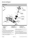
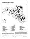
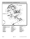
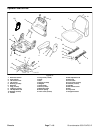
Removal (Fig. 10)
1. Park machine on a level surface, lower cutting
decks, stop engine, engage parking brake and remove
key from the ignition switch.
2. Remove cutting deck from lift arm (see Cutting Deck
Operator’s Manual).
3. Removelift cylinder pin(item 10)that secureslift cyl-
inder to lift arm.
4. Loosen andremove lock nut(item 17)from pivot pin.
5. Support lift armand pull lift arm pivot pin from liftarm
and frame. Locate and remove thrust washer (item 14)
from rear of lift arm during pivot pin removal.
6. Remove lift arm from machine.
7. Disassemble lift arm as needed using Figure 10 as
a guide.
8. Clean lift arm and pivot pin. Inspect lift arm bushings
and pivotpin fordamage orwear. Replaceworn ordam-
aged components.
Installation (Fig. 10)
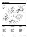
1. Assemble lift arm using Figure 7 as a guide.
2. Position lift arm to frame ( Fig. 10). Fit thrust washer
(item 14) between rear of lift arm and frame. Slide pivot
pin into frame and lift arm. Align roll pin in pivot pin with
slot in frame flange.
3. Install andtighten locknut (item 17)to secure liftarm
pivot pin.
4. Secure lift cylinder to lift arm with cylinder pin (item
10). Secure cylinder pin to lift arm with flange head
screw and flange nut.
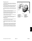
NOTE: Install thrust washer on deck pivot shaft before
installing cutting deck on pivot shaft.
5. Position and install cutting deck to lift arm (see Cut-
ting Deck Operator’s Manual).
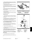
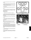
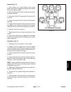
NOTE: The lift arms for cutting decks #2 and #3 are
fitted witha liftarm rotation stopblock (item 3).This stop
isto keepthe deckstable whileraised.To adjustrotation
stop,remove two(2)set screwsfrom stopand fullyraise
cutting deck to position the stop. Apply Loctite #242 (or
equivalent) to set screws and install set screws to se-
cure stop. The rotation stop should c ontact the lift arm
across the full width of the stop.
6. Lubricate lift arm and lift cylinder grease fittings after
assembly is complete.
7. After assembly, raise and lower the cutting deck to
verify that hydraulic hoses and fittings do not contact
anything.
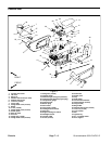
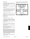
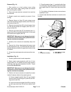
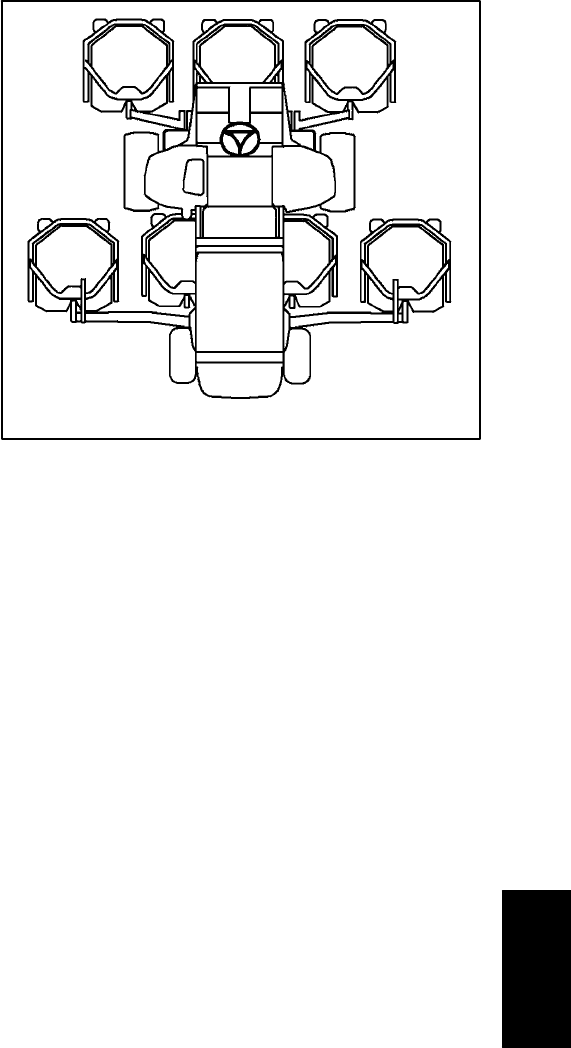
Figure 11
#4 Deck #1 Deck #5 Deck
#7 Deck
(GM4700)
#6 Deck
(GM4700)
#3
Deck
#2
Deck
CUTTING DECK LOCATIONS
Chassis