


Groundsmaster 4500--D/4700--D Hydraulic SystemPage 4 -- 17
Lower Cutting Decks: Groundsmaster 4500--D
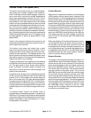
A four section gear pump is coupled to the piston (trac-
tion) pump. Gear pump section P3 supplies hydraulic
flowto boththe liftcontrol manifoldand thesteeringcon-
trol valve.Hydraulic flow fromthis pumpsection is deliv-
ered to the circuits through a proportional flow divider
located in the fan control manifold. Maximum lift/lower
circuitpressureislimitedto1600PSI(110bar)bya relief
valve (R1)in thelift controlmanifold. Liftcircuit pressure
can be monitored at lift control manifold test fitting G1.
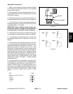
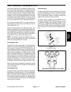
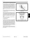
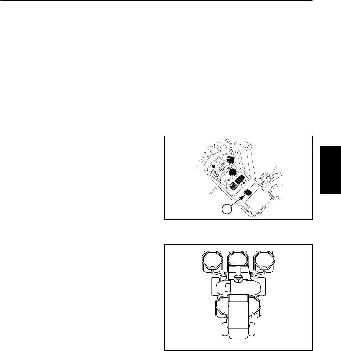
On the Groundsmaster 4500--D, a single lift switch on
the console arm is used to raise and lower the five (5)
cutting decks (Fig. 10).
When the cutting decks are in a stationary position (not
raising or lowering), lift circuit flow from gear pump sec-
tion P3 bypasses the liftcylinders through the lift control
manifold solenoid valve S5 (de--energized) and propor-
tional relief valve TS. Return flow from the manifold is
routed to the oil filter and traction charge circuit.
NOTE: The operator must be in the operator seat in or-
der to lower the cutting decks. Also, when in high speed
(2WD), the cutting decks will not lower.
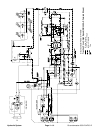
Cutting Deck Lower
To lower the five (5) cutting decks on a Groundsmaster
4500--D, the front of the lift switch is depressed. The
switchactsasaninputtotheTEC--5002controllerwhich
then provides an electrical output to solenoid valve S6
in thelift controlmanifold. Thisenergized solenoidvalve
shifts to allow a passage for o il flow from the rod ends
ofthe five(5)deck liftcylinders.The weightof thecutting
decks causes the lift cylinders to extend and lowers all
of the cutting decks. An orifice in the lift control manifold
restricts oil flow from the lift cylinders to control deck
drop speed. Additionally, an orifice in the junction man-
ifold further controls the lowering speed of the #1 deck.
Whenthe deckswitch isreleased, thesolenoid valveS6
is de--energized and the lift cylinders and cutting decks
are held in position.
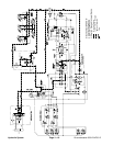
Cutting Deck Float
Cutting deck float allows the fully lowered cutting decks
to followground surfacecontours. Ona Groundsmaster
4500--D, lift control manifold solenoid valve S6 is ener-
gized for deck float when the decks are fully lowered.
This energized solenoid provides an oil passage to and
from the lift cylinders to allow cylinder and cutting deck
movement while mowing.
Counterbalance
Once the cutting decks are fully lowered, the lift control
manifold proportional relief valve (TS) maintains back
pressure (counterbalance) on the deck lift cylinders.
This counterbalance pressure transfers cutting deck
weight to the machine to improve traction.
A pressure sensor located in the 4WD/2WD control
manifold isused bythe TEC--5002 controlleras aninput
to determine traction circuit pressure. Based on this
sensor input, a PWM (Pulse Width Modulation) signal
from the TEC--5002 controller is provided to the propor-
tional relief valve (TS) tomaintain counterbalance pres-
sure.
1. Lift switch (#1 to #5)
Figure 10
1
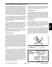
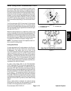
Figure 11
#4 #1 #5
#3#2
GM--4500 CUTTING DECK LOCATIONS
Hydraulic
System