


Groundsmaster 4500--D/4700--D Hydraulic SystemPage 4 -- 31
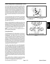
Engine Cooling Fan Circuit
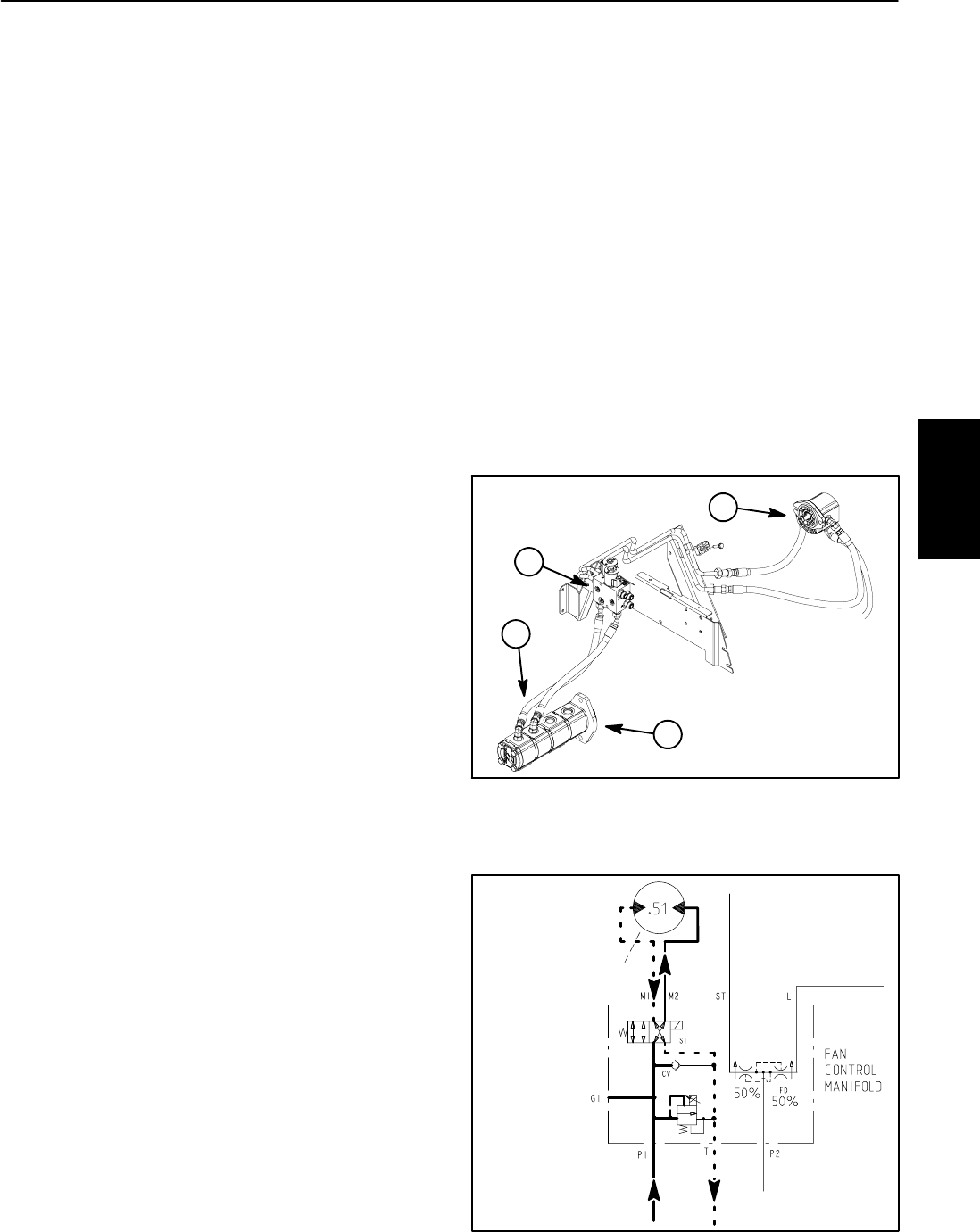
A four section gear pump is coupled to the piston (trac-
tion) pump.The gearpump sectionP4 (farthestfromthe
piston pump) supplies hydraulic flow for the hydraulic
engine cooling fan motor (Fig. 24).
Thefancontrolmanifoldcontrols theoperationofthehy-
draulic motor that drives the engine cooling fan in addi-
tion to including the flow divider for the steering and lift
circuits. The electronically controlled proportional relief
valve (TS) in the manifold controls the oil flow to the fan
motor. The fan control manifold controls the speed and
directionof the fanmotorbased onelectrical outputfrom
the TEC--5002 controller.
Oil flow from the gear pump to the cooling fan motor is
controlled by the proportional relief valve (TS) in the fan
control manifold. This valve adjusts fan circuit flow
based on a PWM (Pulse Width Modulation) signal from
the TEC--5002 controller. The controller uses engine
coolant and hydraulic oil temperatures as inputs to de-
termine the properPWM signalfor the TSvalve. Thefan
circuit flow determines the speed of the cooling fan mo-
tor.
The fan motor runs at half speed until coolant reach-
es approximately 165
o
F(74
o
C). The fan motor in-
creases to full speed (approximately 2800 RPM) as
coolant reaches 180
o
F(82
o
C).
The fan motor automatically reverses if coolant
reaches203
o
F(95
o
C)orhydraulic oilreaches212
o
F
(100
o
C).
If the fan motor is stalled for any reason, the manifold
proportional relief valve (TS) has a s econdary function
as a circuit relief to limit fan motor pressure to 3000 PSI
(207 bar).
When the engine is shut off, the over--running inertia
load of the fan blades keeps driving the fan motor and
turnsit intoapump. Thecheck valve(CV) inthe fancon-
trol manifold will open to keep the motor circuit full of oil
so the fan motor will not cavitate.
NOTE: IfPWM currentis notavailable tothe fancontrol
manifold proportional relief valve (TS), the cooling fan
motor will run at full speed in the normal (forward) direc-
tion.
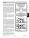
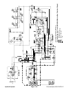
Forward Direction Fan Operation
Oilflow fromthe gearpump issentthrough thede--ener-
gized solenoid v alve S1 to rotate the cooling fan motor.
Return flow from the motor re--enters the manifold (port
M2),through thede--energized solenoidvalve S1,outof
themanifold (portT) andthenis routedthrough thedeck
control manifold, oil cooler and oil filter.
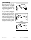
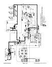
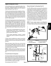
Reverse Direction Fan Operation (Fig. 25)
The TEC--5002 controller can reverse the cooling fan to
clean debris from the rear intake screen. If hydraulic oil
and/or engine coolant temperatures increase to an un-
suitable level or if the engine cooling fan switch is
pressed to manual reverse, a high PWM signal is sent
to the TS valve to slow the cooling fan and direct pump
oil flow away from the fan motor. The controller then en-
ergizes solenoid valve S1 in the fan control manifold to
reverse cooling fan motor oil flow so that the motor runs
in the reverse direction. A lower PWM signal is sent to
the TS valve allowing oil flow to return to the fan motor
but in the reverse direction causing the motor and cool-
ing fan to run in reverse for a short time.
NOTE: The fan reversal process is not designed to
clean the radiator of debris. Refer to Operator’s Manual
for radiator cleaning maintenance recommendations.
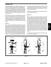
1. Gear pump
2. Fan control manifold
3. Fan circuit supply hose
4. Hydraulic fan motor
Figure 24
1
2
3
4
Figure 25
REVERSE
FROMGEAR
TOOILCOOLER
TORESERVOIR
TOLIFT/LOWER
CIRCUIT
TOSTEERING
CIRCUIT
PUMP(P3)
FROMGEAR
PUMP(P4)
DIRECTION
TS
Hydraulic
System