


Groundsmaster 4500--D/4700--D Page 3 -- 17 Kubota Diesel Engine
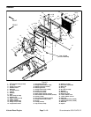
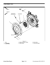
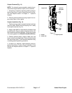
Coupler Removal (Fig. 14)
NOTE: The hydraulic pump assembly needs to be re-
moved from engine before coupler can be removed.
1. If engine is in machine, remove hydraulic pump as-
sembly(seePiston(Traction)PumpRemovalin theSer-
vice and Repairs section of Chapter 4 -- Hydraulic
System).
2. Remove flywheel plate and spring coupler from en-
gine using Figure 14 as a guide.
Coupler Installation (Fig. 14)
1. Position spring coupler to engine flywheel and align
mounting holes. Make sure that coupling hub is away
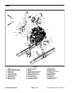
from engine flywheel (Fig. 15).
2. Apply Loctite #242 (or equivalent) to threads of cap
screws (item 6). Secure coupler to flywheel with six (6)
cap screws and hardened washers. Torque cap screws
in acrossing pattern from29 to 33ft--lb (40to 44 N --m).
3. Position flywheel plate to engine. Make sure that
boss on plate is orientated down. Secure flywheel plate
with cap screws (item 7) and hardened washers using
a crossing pattern tightening procedure.
4. If engine is in machine, install hydraulic pump as-
sembly (see Piston (Traction) Pump Installation in the
Service and Repairs section of Chapter 4 -- Hydraulic
System).
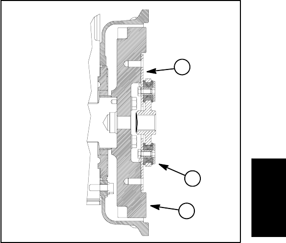
Figure 15
1. Coupler
2. Coupler hub
3. Engine flywheel
Engine Side Hydraulic
Pump Side
1
2
3
Kubota
Diesel Engine