


Groundsmaster 4500--D/4700--D Hydraulic SystemPage 4 -- 47
NOTE: Adjustable relief valve (RV) in the 4WD/2WD
control manifold reduces rear axle motor pressure
created in down hill, dynamic braking conditions to pre-
vent rear wheel lock up.
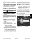
Procedurefor RearTraction CircuitRelief (RV)Pres-
sure Test
1. Make sure hydraulic oil is at normal operating tem-
peraturebyoperatingthemachineforapproximatelyten
(10) minutes. Make sure the hydraulic tank is full.
2. Park machine on a level surface with the cutting
decks lowered and off. Make sure engine is off and the
parking brake is engaged.
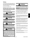
CAUTION
Prevent personal injury and/or damage to equip-
ment. Read all WARNINGS, CAUTIONS and Pre-
cautions for Hydraulic Testing at the beginning
of this section.
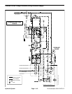
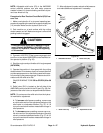
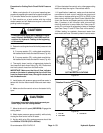
3. Connect a 1000 PSI (70 bar) pressure gauge to test
port Gon onrear sideof 4WD/2WD controlmanifold un-
der operator’s platform (Fig. 36).
4. Start the engine and put throttle at full engine speed
(2870 RPM).
5. Operate the machine in Low speed with the cutting
deckslowered.Drivedown aslopein aforwarddirection
and decreasepressure onthe traction pedalwhile care-
fullymonitoringthe pressuregauge.Pressureshouldin-
crease until the relief valve lifts.
GAUGEREADINGTOBE520 to 570 PSI (36 to 39
bar)
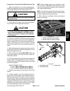
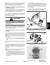
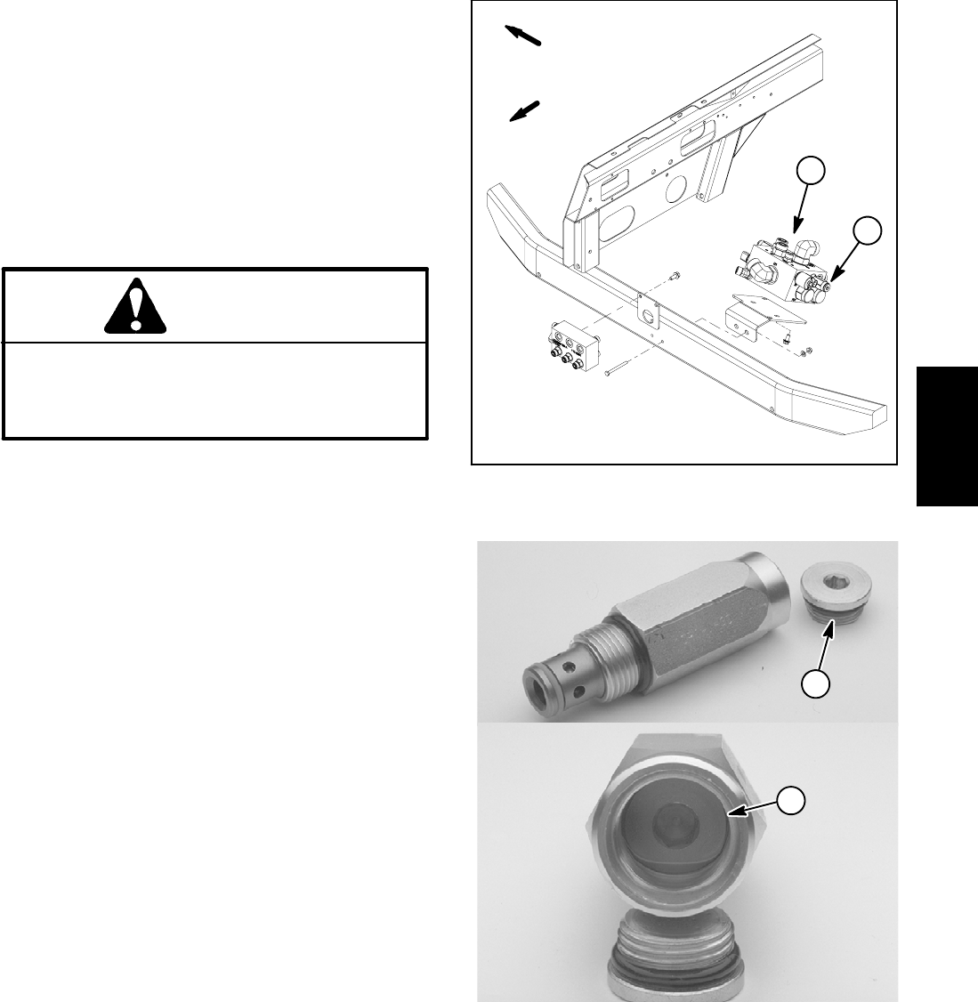
6. Relief valve (RV) is located on the left side of the
4WD/2WD control manifold in the RV port (Fig. 36). Ad-
justment of the relief valve can be performed as follows:
NOTE: Do not remove the relief valve from the hydrau-
lic manifold for adjustment.
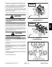
A. To increase relief pressure setting, remove cap
on relief valve and turn the adjustment socket on the
relief valve in a clockwise direction (Fig. 37). A 1/8
turn on thesocket will make ameasurable change in
relief pressure.
B. To decreasepressure setting,remove cap onre-
lief valveand turn theadjustment socket onthe relief
valve in a counterclockwise direction (Fig. 37). A 1/8
turn on thesocket will make ameasurable change in
relief pressure.
C. Afteradjustment ismade, recheckr elief pressure
and make additional adjustment if necessary.
1. 4WD/2WD manifold 2. Relief valve (RV)
Figure 36
1
2
FRONT
RIGHT
Figure 37
1. Relief valve cap 2. Adjustment socket
1
2
Hydraulic
System