


Groundsmaster 4500--D/4700--D Hydraulic SystemPage 4 -- 89
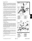
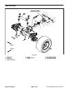
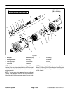
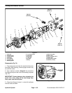
Removal (Fig. 70)
1. Park machine on a level surface, lower cutting
decks, stop engine, engage parking brake and remove
key from the ignition switch.
2. Raise front of machine and support with jackstands.
3. Read the General Precautions for Removing and
Installing Hydraulic System Components at the begin-
ning of the Service and Repairs section of this chapter.
4. Toprevent contamination ofhydraulic system during
wheel motor removal, thoroughly clean exterior of mo-
tor.
5. Disconnect hydraulic hoses and tubes from wheel
motor. Putcaps orplugs on hosesand fittingsto prevent
contamination. Label the hydraulic lines to show their
correct position on the wheel motor for assembly pur-
poses.
IMPORTANT: Support wheel motor to prevent mo-
tor from falling during removal.
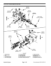
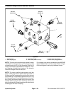
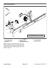
6. Remove wheel motor using Figure 70 as a guide.
7. Ifhydraulicfittings areto beremovedfrom wheelmo-
tor, mark fitting orientation to allow correct assembly.
Remove fittings from motor and discard O--rings.
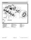
Installation (Fig. 70)
1. If fittings were removed from wheel motor, lubricate
and place new O--rings onto fittings. Install fittings into
motor ports using marks made during the removal pro-
cess to properly orientate fittings. Tighten fittings (see
Hydraulic Fitting Installation in the General Information
section of this chapter).
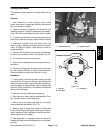
2. Positionwheelmotortobrakeassembly makingsure
that arrows on the side of motor case point upward.
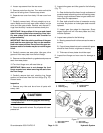
3. Align splines onmotor shaft and splined brakeshaft.
Slide motor into brake assembly.
4. Secure motor to brake assembly with cap screws
andflat washers.Tighten capscrews from75 to85 ft--lb
(102 to 115 N--m).
5. Removeplugs from linesand fittings. Attach hydrau-
lic lines and tubes to wheel motor (see Hydraulic Hose
and Tube Installation in the GeneralInformation section
of this chapter).
6. Lower machine to ground.
7. Fill reservoir with hydraulic fluid as required.
Hydraulic
System