


Groundsmaster 4500--D/4700--D Hydraulic SystemPage 4 -- 53
Procedure for Cutting Deck Circuit Relief Pressure
Test
1. Make sure hydraulic oil is at normal operating tem-
peraturebyoperatingthemachineforapproximatelyten
(10) minutes. Make sure the hydraulic tank is full.
2. Park machine on a level surface with the cutting
decks lowered and off. Make sure engine is off and the
parking brake is engaged.
CAUTION
Prevent personal injury and/or damage to equip-
ment. Read all WARNINGS, CAUTIONS and Pre-
cautions for Hydraulic Testing at the beginning
of this section.
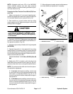
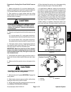
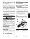
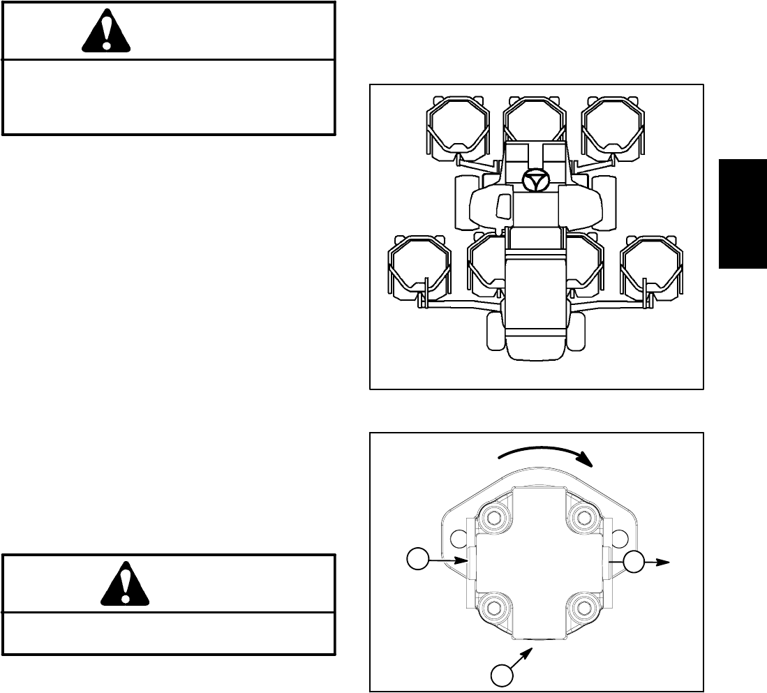
3. Determinecuttingdeck manifold reliefpressuretobe
tested:
A. For pump section (P1), cutting deck manifold re-
liefis testedatthe inlettothe deck#5motor (Fig.44).
B. For pump section (P2), cutting deck manifold re-
liefis testedatthe inlettothe deck#1motor (Fig.44).
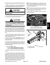
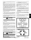
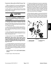
4. Thoroughly clean junction of appropriate hydraulic
inlet hose and deck motor fitting (Fig. 45). Disconnect
the inlet hydraulic hose from the deck motor.
IMPORTANT: Make sure that the oil flow indicator
arrow on the tester is showing that the oil will flow
from the disconnected hose,through the tester and
into the deck motor.
5. Install tester with pressure gauge and flow meter in
series with the the disconnected hose and deck motor
inlet.
6. Make sure the flow control valve on the tester is fully
open.
CAUTION
Keepawayfromdecks duringtest topreventper-
sonal injury from the cutting blades.
7. Move throttle to full speed (2870 RPM). Engage the
cutting decks.
8. Watch tester pressure gauge carefully while slowly
closing the flow control valve on tester.
9. As the relief valve lifts, system pressure should be
from 3400 to 3750 PSI (235 to 258 bar).
10.Open thetester flowcontrol valve,disengage cutting
decks and stop the engine. Record test results.
11.If specification is not met, make sure that electrical
connections at deck control manifold are secure and
then clean or replace relief valve (PRV1 or PRV2) in the
deck control manifold (see Deck Control Manifold Ser-
vice in the Service and Repairs section of this chapter).
Also, if pressure is still low after relief valve service,
check for restriction in pump intake line. Gear pump P1
and/or P2 could also be suspected of wear or damage
(see Gear Pump P1 and P2 Flow Test in this section).
12.After testing is complete, disconnect tester from
deck motor and hose. Connect hydraulic hose to motor.
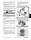
Figure 44
#4 Deck #1 Deck #5 Deck
#7 Deck
(GM4700)
#6 Deck
(GM4700)
#3
Deck
#2
Deck
CUTTING DECK LOCATIONS
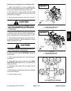
1. Flow IN
2. Flow OUT
3. Case drain
Figure 45
Rotation Direction
2
1
3
Hydraulic
System