


Groundsmaster 4500--D/4700--D Page 6 -- 25 Axles, Planetaries and Brakes
5. Install a new stake washer. Install the lock nut finger
tight.
6. Setthe bearingpreloadby securingthebearing case
in a vise. Thread a M12 x 1.5 hex head cap screw into
the splined end of the input shaft/pinion gear and slowly
tighten the lock nut until 4 to 6 in-lb (0.4 to 0.7 N--m) of
force is required to rotate the input shaft/pinion gear in
the bearing case.
7. Secure the lock nut with the stake washer.
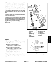
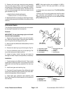
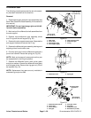
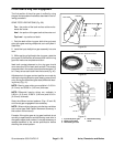
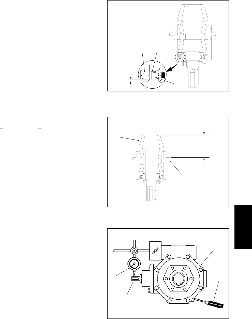
8. Use adepth gauge tomeasure thedistance from the
end face ofthe input shaft/pinion gear tothe mating sur-
face of the bearing case. Subtract the “Design Cone
Center Distance” from this distance to determine initial
shim thickness (Fig. 30).
DESIGN CONE CENTER DISTANCE
(distance from mating surface of axle support to end
face of pinion gear):
1.870 +
0.002 in. (47.5 + 0.05 mm)
NOTE: Bearing case shims are available in 0.004 in.
(0.1 mm) and 0.008 in. (0.2 mm) thickness.
9. Coatnew O-rings with greaseand install the bearing
casein thegear case.Place shimson thegear caseand
temporarily install gear case assembly into axle case.
Tighten mounting nuts and screws from 35 to 41 ft-lb
(47to56N--m).
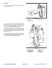
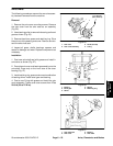
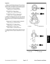
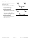
10.Insert a screwdriver through the drain plug hole to
hold r ing gear and measure the pinion gear to ring gear
backlash (Fig. 31).
PINION GEAR TO RING GEAR BACKLASH:
0.004 to 0.016 in. (0.10 to 0.40 mm)
11.Adjust backlashby increasing or reducinggear case
shim thickness.
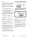
12.Checkpiniongear toringgearengagement(seePin-
ion Gearto RingGear Engagementin thissection ofthis
manual).
13.Place the correct combination of shims on the gear
case. Tighten mounting nuts and screws from 35 to 41
ft-lb (47 to 56 N--m).
14.Install retaining rings and driven gear on input shaft/
pinion gear.
15.If the drive gear (on drive motorshaft) was removed,
install the retaining rings and drive gear on the motor
shaft.
16.Use a new gasket and install the cover plate. Use a
new O-ring and install the drive motor.
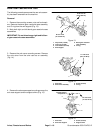
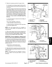
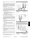
1. Oil seal
2. Bearing case
3. Seal garter spring
Figure 29
1
2
3
0.040 in. (1.0 mm)
1. Input shaft/pinion gear 2. Bearing case
Figure 30
1
2
Design
Cone Center
Distance
1. Axle case
2. Screwdriver
3. Dial indicator
4. Input shaft/pinion gear
Figure 31
1
2
3
4
Axles, Planetaries
and Brakes