


Groundsmaster 4500--D/4700--DPage 5 -- 16Electrical System
Fuses
Groundsmaster 4500--D and 4700--D use numerous
fuses for circuit protection. The fuses are located in two
(2) areas of the machine. Most of the fuses reside in the
power centerbehind theoperator’sseat. Anin--line fuse
holder locatedin the wire harnessnear the engine start-
er motor holds an additional fuse (F5--1) that protects
the engine run solenoid circuit.
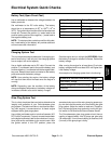
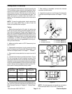
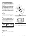
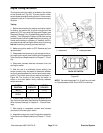
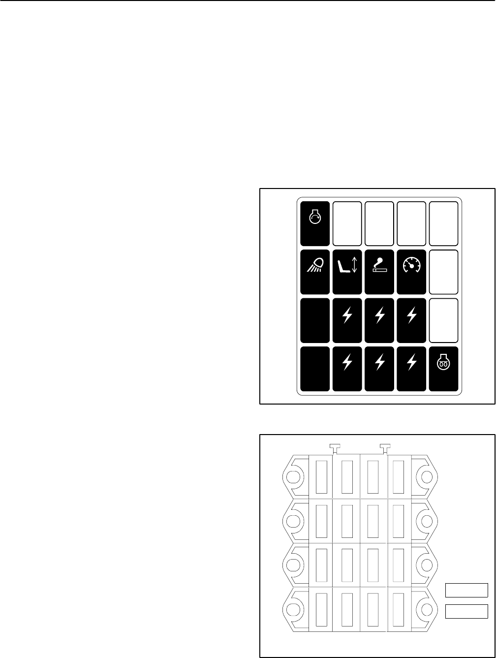
Fuse Identification and Function (Figs. 14 and 15)
Fuse F1--1 (20 Amp) supplies power to engine starter
circuit.
Fuse F1--2 positionavailable foroptional flowdivider kit.
Fuse F1--3 position available for optional kit.
Fuse F1--4 position available for optional kit.
Fuse F2--1 (10 Amp) supplies power to the light circuit.
FuseF2--2(10Amp)suppliespower totheoperatorseat
circuit.
Fuse F2--3 (10 Amp) supplies power to the powerpoint.
Fuse F2--4 (10 Amp) supplies power to the main power
circuit.
Fuse F3--1 (2 Amp) supplies logic power to the
TEC--5002 controller.
Fuse F3--2 (7.5 Amp) supplies power to the TEC--5002
controller.
Fuse F3--3 (7.5 Amp) supplies power to the TEC--5002
controller.
Fuse F3--4 (7.5 Amp) supplies power to the TEC--5002
controller.
Fuse F4--1 (2 Amp) supplies logic power to the
TEC--5001 controller.
Fuse F4--2 (7.5 Amp) supplies power to the TEC--5001
controller.
Fuse F4--3 (7.5 Amp) supplies power to the TEC--5001
controller.
Fuse F4--4 (7.5 Amp) supplies power to the TEC--5001
controller.
Fuse M1 (60A) supplies power to the glow plug circuit.
Fuse M2 position available for operator cab option.
Fuse F5--1 ( in--line 40A) supplies power for the engine
run solenoid.
Fuse Testing
1. Make sure that ignition switch is OFF and key is re-
moved from switch.
2. Remove power center cover from operator platform
to access fuses.
3. Remove fuse from fuse block for testing. Fuse
should have continuity across the terminals.
4. After fuse testing is completed, install and secure
power center cover.
Figure 14
10A
20A
10A
10A
10A
2A
7.5A
7.5A
7.5A
2A
GM 4700
TEC- -5001
GM 4500
TEC- - 5002
7.5A
7.5A
7.5A 60A
Figure 15
4321
F4
FRONT
2A
F3
F2
F1
7.5 A
7.5A
7.5A
2A
7.5A
7.5A
7.5A
10A
10A
10A
10A
20A
OPTION
OPTION
OPTION
M1 (60A)
M2 (option)