


Groundsmaster 4500--D/4700--D Hydraulic SystemPage 4 -- 81
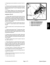
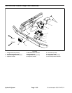
Removal (Fig. 64)
NOTE: Theports on the manifolds are marked foreasy
identification of components. Refer to the Hydraulic
Schematics in Chapter 9 -- Foldout Drawings to identify
the function of the hydraulic lines and cartridge valves
at each port.
1. Read the General Precautions for Removing and
Installing Hydraulic System Components at the begin-
ning of the Service and Repairs section of this chapter.
2. Toprevent contamination ofhydraulic system during
manifold removal,thoroughly cleanexterior ofmanifold.
3. If 4WD/2WD control manifold is being removed, la-
bel wire harness electrical connectors that attach to
manifold components. Disconnect harness electrical
connectors from the solenoid v alve coil and electrical
sensors (pressure and temperature).
4. Disconnect hydraulic lines from manifold being re-
moved and put caps or plugs on open hydraulic lines
andfittings. Labeldisconnected hydrauliclines forprop-
er assembly.
5. Remove hydraulic manifold from the frame using
Figure 64 as guide.
6. If hydraulic fittings are to be removed from control
manifold,mark fittingorientation toallowcorrect assem-
bly (Figure 65or 66). Remove fittingsfrom manifold and
discard O--rings.
Installation (Fig. 64)
1. If fittings were removed from control manifold, lubri-
cate and place new O--rings onto fittings. Install fittings
into manifoldports usingmarks madeduring theremov-
al process to properly orientate fittings. Tighten fittings
(see Hydraulic Fitting Installation in the General Infor-
mation section of this chapter). Refer to Figure 65 or 66
for fitting installation torque.
2. Install hydraulic manifold to the frame using Figure
64 as guide.
3. Remove caps and plugs from fittings and hoses.
Properly connect hydraulic lines to manifold (see Hy-
draulic Hose and Tube Installation in the General Infor-
mation section of this chapter).
4. If4WD/2WDcontrol manifoldwasremoved,connect
wire harness electrical connectors to the solenoid valve
coil and electrical sensors.
5. Fill hydraulic reservoir with hydraulic fluid as re-
quired.
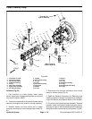
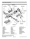
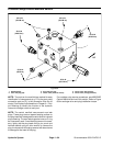
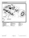
1. 4WD/2WD manifold
2. O--ring
3. 45
o
fitting
4. O--ring
5. 90
o
fitting
6. Straight fitting
7. O--ring
8. O--ring
9. Check fitting
10. O--ring
11. O--ring
12. Straight fitting
13. O--ring
14. Test fitting
15. Dust cap
Figure 65
4
2
6
5
7
3
1
8
9
2
2
4
4
5
6
10
12
11
13
14
15
50 ft--lb
(68 N--m)
75 ft--lb
(101 N--m)
25 ft--lb
(33.9 N--m)
20 ft--lb
(27.1 N--m)
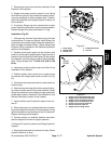
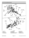
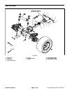
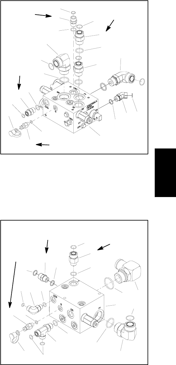
1. Filtration manifold
2. O--ring
3. 90
o
fitting
4. O--ring
5. Straight fitting
6. O--ring
7. Straight fitting
8. O--ring
9. O--ring
10. 90
o
fitting
11. O--ring
12. Test fitting
13. Dust cap
14. Tee fitting
15. O--ring
16. 90
o
fitting
17. O--ring
Figure 66
4
2
6
5
7
3
1
8
9
4
4
8
8
10
11
12
13
14
15
16
17
50 ft--lb
(68 N--m)
25 ft--lb
(33.9 N--m)
20 ft--lb
(27.1 N--m)
Hydraulic
System