


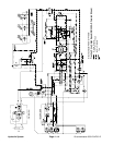
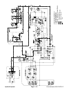
Groundsmaster 4500--D/4700--D Hydraulic SystemPage 4 -- 9
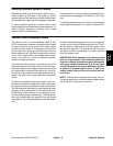
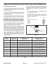
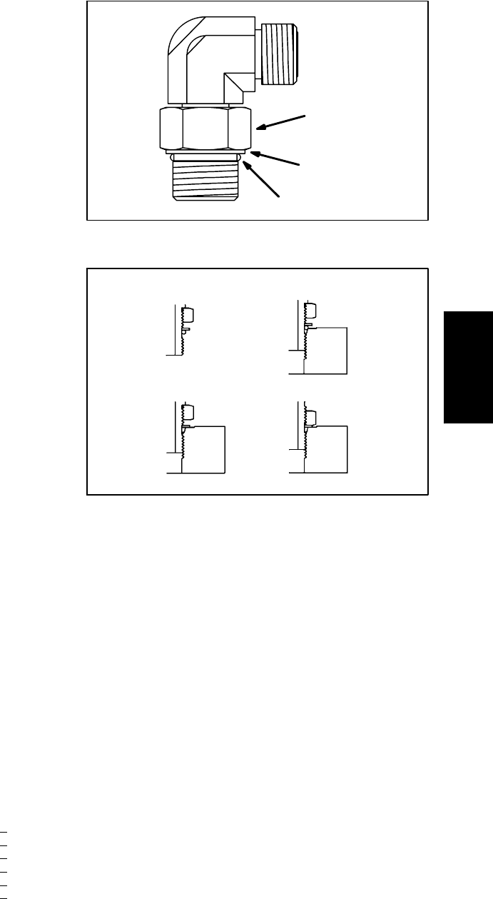
Adjustable Fitting (Fig. 8)
1. Make sure all threads and sealing surfaces of fitting
and component port are free of burrs, nicks, scratches
or any foreign material.
2. As apreventative measure againstleakage, itis rec-
ommended that the O--ring be replaced any time the
connection is opened.
3. Lightly lubricate the O--ring with clean hydraulic oil.
Fittingthreadsshould beclean withnolubricant applied.
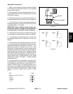
4. Turn back the lock nut as far as possible. Make sure
the back up washer is not loose and is pushed up as far
as possible (Step 1 in Figure 9).
IMPORTANT: Before installing fitting into port, de-
termine port material. If fitting is to be installed into
an aluminum port, installation torque is reduced.
5. Install the fitting into the port and tighten finger tight
until the washer contacts the face of the port (Step 2).
6. Toput the fittingin the desiredposition, unscrew itby
the required amount, but no more than one full turn
(Step 3).
7. Hold the fitting in the desired position with a wrench
and use a torque wrench to tighten the fitting to the rec-
ommended installation torque shown in Figure 7. This
tightening process will require the use of an offset
wrench (e.g. crowfoot wrench). Use of an offset wrench
will affect torque wrench calibration due to the effective
length change of the torque wrench. Tightening torque
when using a torque wrench with an offset wrench will
be lower than the listed installation torque (see Using a
Torque Wrench with an Offset Wrench in the Torque
Specifications section of Chapter 2 -- Product Records
and Maintenance).
8. If a torque wrench is not available, or if space at the
portprevents useof atorque wrench,an alternatemeth-
od of assembly is the Flats From Finger Tight (F.F.F.T.)
method. Hold the fitting in the desired position with a
wrench and, if port material is steel, tighten the lock nut
witha secondwrench tothelisted F.F.F.T(Step4). Ifport
material is aluminum, tighten fitting to 60% of listed
F.F.F.T.
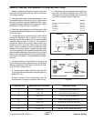
Size F.F.F.T.
4 (1/4 in. nominal hose or tubing) 1.00 +
0.25
6(3/8in.) 1.50+
0.25
8(1/2in.) 1.50+
0.25
10 (5/8 in.) 1.50 +
0.25
12 (3/4 in.) 1.50 +
0.25
16 (1 in.) 1.50 +
0.25
Figure 8
Lock Nut
Back--up Washer
O--ring
Figure 9
Step 3Step 1
Step 2 Step 4
Hydraulic
System