


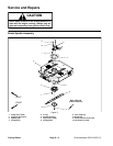
Groundsmaster 4500--D/4700--D Cutting DecksPage 8 -- 9
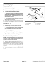
Removal (Fig. 3)
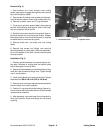
1. Park machine on a level surface, lower cutting
decks, stop engine, engage parking brake and remove
key from the ignition switch.
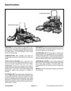
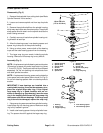
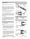
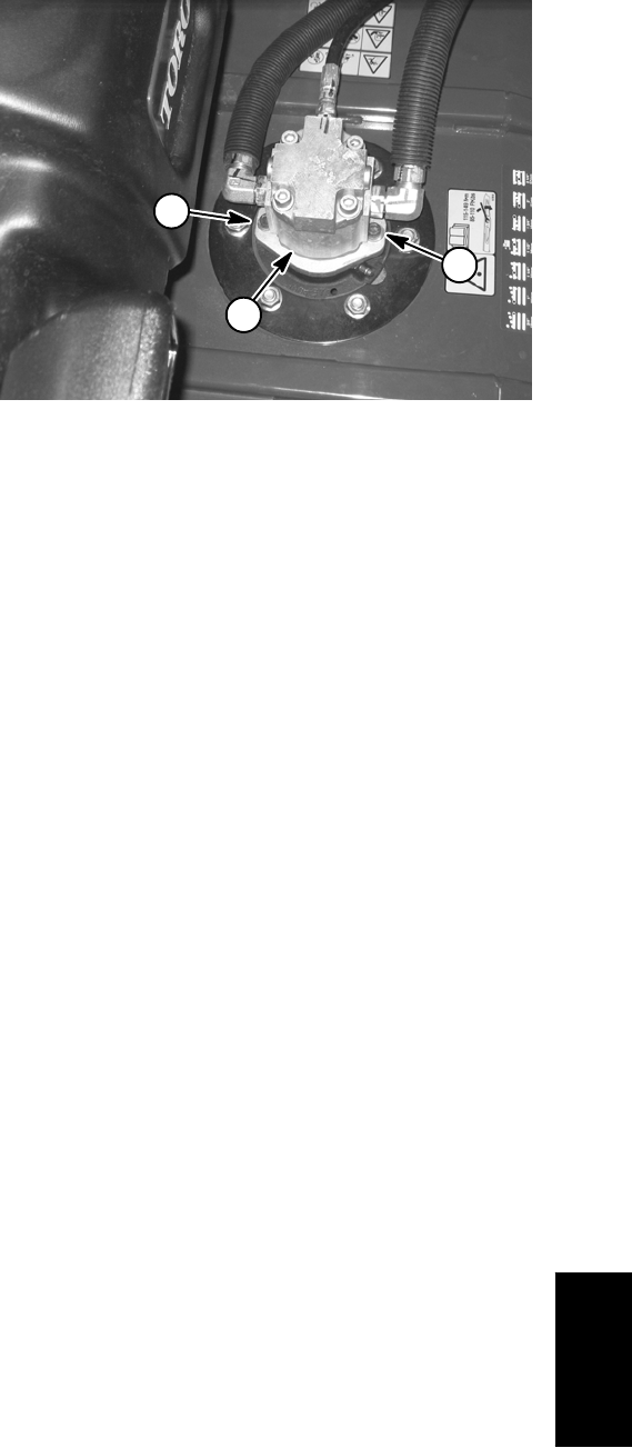
2. Remove two (2) socket head screws and flat wash-
ers that secure hydraulic motor to the cutting deck (Fig.
4). Remove hydraulic motor and O--ring from deck.
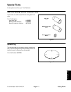
3. Cover top of spindle to prevent debris from entering
spindle. A spindle plug (see Special Tools in this chap-
ter) can be used to c over spindle.
4. Start the engine and raise the cutting deck. Stop en-
gine and remove key from the ignition switch. Support
the cutting deck so it cannot fall accidentally. If required
for easier service, remove cutting deck.
5. Remove blade bolt, anti--scalp cup and cutting
blade.
6. Remove cap screws and flange nuts securing
spindle assembly to cutting deck. Slide spindle assem-
bly out the bottom of the deck. Remove spindle plate
from top of deck.
Installation (Fig. 3)
1. Position spindle assembly and spindle plate to cut-
ting deck. Notches on cutting deck and spindle plate
should be aligned to front of deck.
2. Securespindleassembly andspindleplate tocutting
deck with cap screws and flange nuts. Tighten flange
nuts in a star pattern.
3. Installcutting blade, anti--scalp cup andbolt. Tighten
blade bolt from 88 to 108 ft--lb (120 to 146 N--m).
4. Remove coverfrom top ofspindle that was placedto
prevent debris from entering spindle.
5. PositionO--ring totop ofspindlehousing. Securehy-
draulicmotortothecuttingdeckwithtwo(2)sockethead
screws and flat washers.
6. After assembly, raise and lower the cutting deck to
verify that hydraulic hoses and fittings do not contact
anything.
1. Socket head screw 2. Hydraulic motor
Figure 4
1
2
1
Cutting Decks