


Groundsmaster 4500--D/4700--DHydraulic System Page 4 -- 118
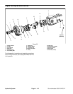
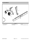
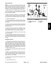
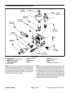
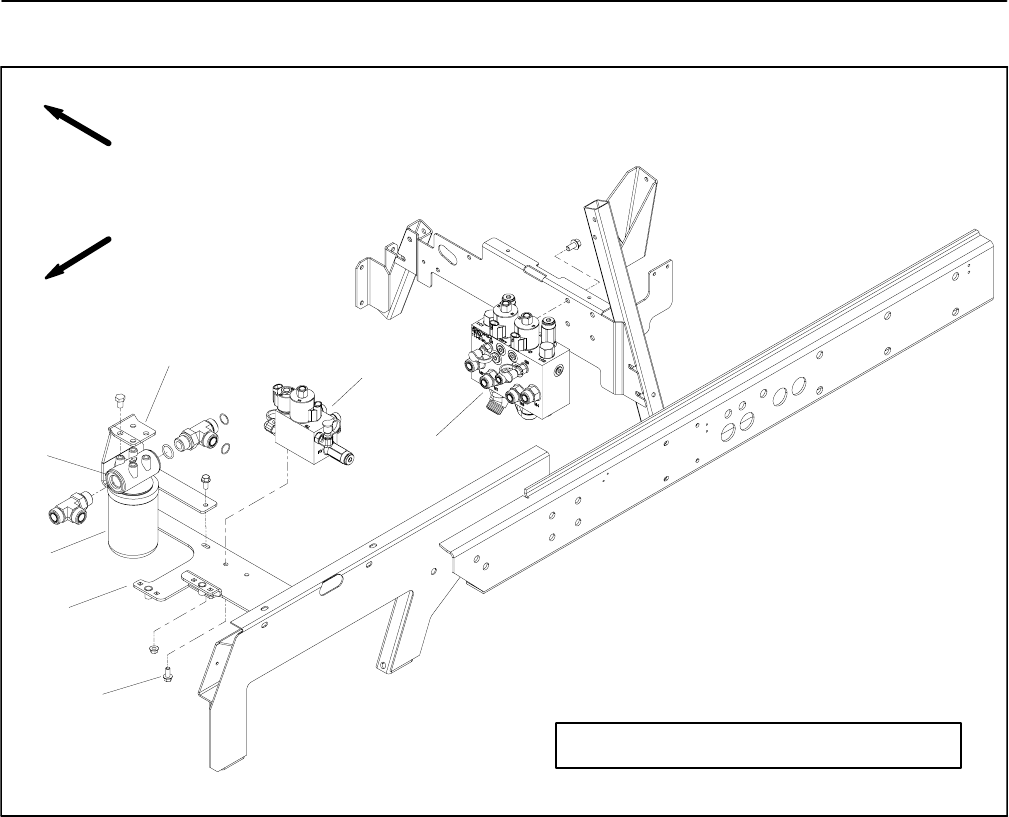
Lift Control Manifold
1. Lift control manifold
2. Filter mount bracket
3. Filter head
4. Hydraulic oil filter
5. Valve mount bracket
6. Flange head screw (2 used)
7. Deck control manifold
Figure 97
FRONT
RIGHT
7
4
6
3
2
1
5
GROUNDSMASTER 4500--D SHOWN
NOTE: Thelift controlmanifolds usedon Groundsmas-
ter 4500--D and 4700--D machines aredifferent butthey
mountto themachinein thesame location. TheGround-
smaster 4500--D control manifolds are shown in Figure
97.
Removal (Fig. 97)
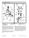
NOTE: The ports on the manifold are marked for easy
identification of components. Example: P1 is the gear
pump connection port (see Hydraulic Schematics in
Chapter 9 -- Foldout Drawings to identify the function of
the hydraulic lines and cartridge valves at each port).
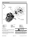
1. Park machine on a level surface, lower cutting
decks, stop engine, apply parking brake and remove
key from the ignition switch.
IMPORTANT: To prevent unexpected deck lower-
ing, make sure that cutting decks are fully lowered
before loosening hydraulic lines from lift manifold.
2. Read the General Precautions for Removing and
Installing Hydraulic System Components at the begin-
ning of the Service and Repairs section of this chapter.
3. Unlatch and raise hood.
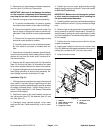
4. Toprevent contamination ofhydraulic system during
manifold removal,thoroughly cleanexterior ofmanifold.
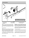
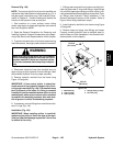
5. Label wire harness electrical connectors that attach
to manifold solenoid coils. Disconnect wire harness
electrical connectors from the solenoid valve coils.