


Groundsmaster 4500--D/4700--D Hydraulic SystemPage 4 -- 127
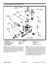
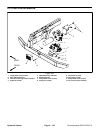
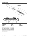
Removal (Fig. 105)
1. Park machine on a level surface, lower cutting
decks, stop engine, engage parking brake and remove
key from the ignition switch.
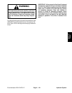
2. Read the General Precautions for Removing and
Installing Hydraulic System Components at the begin-
ning of the Service and Repairs section of this chapter.
3. Toprevent contamination ofhydraulic system during
lift cylinder removal, thoroughly clean exterior of lift cyl-
inder.
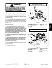
WARNING
Make sure that cutting decks are fully lowered
before loosening hydraulic lines from lift cylin-
der. If decks are raised as hydraulic lines are
loosened, decks may drop unexpectedly.
4. Disconnect hydraulic hoses from lift cylinder. Put
caps or plugs on open hydraulic linesand fittings to pre-
vent system contamination. Label disconnected hy-
draulic lines for proper assembly.
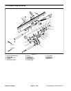
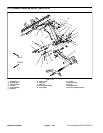
5. Remove flange nut and flange head screw that se-
cure the cylinder pin (item 4) to the lift arm. Remove pin
from lift arm and cylinder shaft clevis which will free lift
cylinder from lift arm.
6. Remove flange nut and flange head screw that se-
cure the cylinderpin (item 13) to theframe. Pull pin from
frame and cylinder barrel clevis.
7. Remove lift cylinder from machine.
8. If hydraulic fittings are to be removed from lift cylin-
der, mark fitting orientation to allow correct assembly.
Remove fittings from cylinder and discard O--rings.
Installation (Fig. 105)
1. If fittings were removed from lift cylinder, lubricate
and place new O--rings onto fittings. Install fittings into
cylinderopeningsusingmarks madeduringtheremoval
process to properly orientate fittings. Tighten fittings
(see Hydraulic Fitting Installation in the General Infor-
mation section of this chapter).
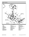
2. Positioncylinder barrelclevis to frameand insertcyl-
inder pin(item 13)into frame andclevis. Secure pinwith
flange nut and flange head screw.
3. Insert cylinder pin (item 4) through lift arm and cylin-
der shaftclevis. Securepin tolift armwith flange nutand
flange head screw.
4. Remove caps and plugs from hoses and fittings. At-
tach hydraulic hoses to lift cylinder (see Hydraulic Hose
and Tube Installation in the GeneralInformation section
of this chapter).
5. Fill reservoir with hydraulic fluid as required.
6. After assembly is completed, operate lift cylinder to
verify thathydraulic hoses and fittingsare notcontacted
by anything.
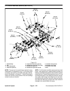
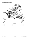
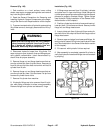
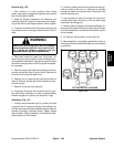
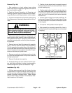
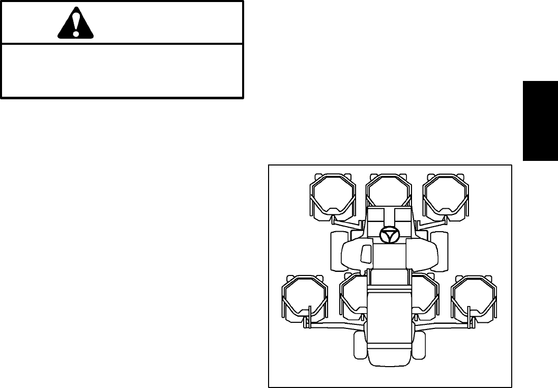
Figure 106
#4 Deck #1 Deck #5 Deck
#7 Deck
(GM4700)
#6 Deck
(GM4700)
#3
Deck
#2
Deck
CUTTING DECK LOCATIONS
Hydraulic
System