


Groundsmaster 4500--D/4700--D Hydraulic SystemPage 4 -- 23
Raise Cutting Decks: Groundsmaster 4700--D
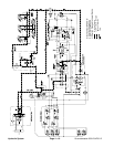
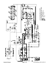
A four section gear pump is coupled to the piston (trac-
tion) pump. Gear pump section P3 supplies hydraulic
flowto boththe liftcontrol manifoldand thesteeringcon-
trol valve.Hydraulic flow fromthis pumpsection is deliv-
ered to the circuits through a proportional flow divider
located in the fan control manifold. Maximum lift/lower
circuitpressureislimitedto1600PSI(110bar)bya relief
valve (R1)in thelift controlmanifold. Liftcircuit pressure
canbe monitoredattest fittingG1on theliftcontrol man-
ifold.
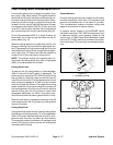
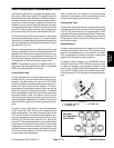
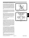
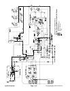
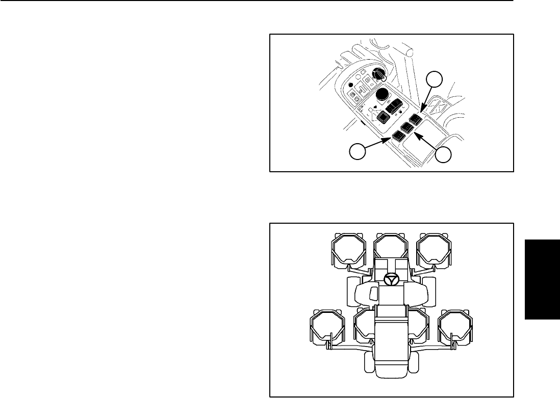
The Groundsmaster 4700--D has three (3) lift switches
to control the cutting decks (Fig. 16). The center switch
isfor thefive (5)center decks,the left switchcontrols the
left,rear deck (#6) and theright switchcontrols theright,
rear deck (#7) (Fig. 17).
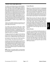
When the cutting decks are in a stationary position (not
raisingor lowering),liftcircuit flowfrom pumpsectionP3
bypasses the lift cylinders through the lift control man-
ifoldsolenoid valveS1 andproportional reliefvalvePRV
which are de--energized. Return flow from the manifold
is routed to the oil filter and traction charge circuit.
NOTE: The operator must be in the operator seat in or-
der to raise the cutting decks.
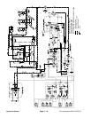
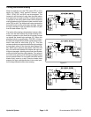
Cutting Deck Raise
To raise the center five (5) cutting decks on the Ground-
smaster 4700--D, the rear of the center console switch
is depressed. The switch acts as an input to the
TEC--5002 controller which then provides an electrical
output to solenoid valves S1 and S5 in the lift control
manifold. The energized solenoid valves shift to allow a
passage for oil flow to the rod ends of the center five (5)
deck lift cylinders. The oil flow causes the lift cylinders
to retract and raises the center five (5) cutting decks.
Two (2) orifices in the junction manifold control the rais-
ing speed of the #2 and #3 decks.
To raise a side cutting deck on the Groundsmaster
4700--D (deck #6 or#7), the rearof the appropriatecon-
sole arm lift switch is depressed. The switch acts as an
inputtotheTEC--5001 controllerwhich thenprovidesan
electricaloutputtotheappropriatesolenoidvalvesin the
lift control manifold: S1 and S2 for deck #6 and S1 and
S7 for deck #7. The energized solenoid valve shifts to
allow a passage for oil flow to the rod ends of the deck
lift cylinder. The oil flow causes the lift cylinder to retract
and raises the cutting deck. An orifice in the lift manifold
restricts oil flow to the lift cylinder to control deck raising
speed.
When a deck switch is released, the solenoid valves
controlled by the switch are de--energized and the lift
cylinders and cutting decks are held in position.
1. Lift switch (#1 to #5)
2. Lift switch (#7)
3. Lift switch (#6)
Figure 16
1
3
2
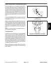
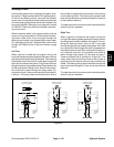
Figure 17
#4 #1 #5
#7#6 #3#2
GM--4700 CUTTING DECK LOCATIONS
Hydraulic
System