


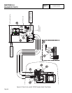
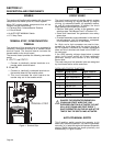
GENERAL
This section will familiarize the reader with the various
components that make up the DC control system.
Major DC control system components that will be
covered include the following:
• ATerminalStrip/InterconnectionTerminal
• ACircuitBoard.
• AnAUTO-OFF-MANUALSwitch.
• A7.5AmpFuse.
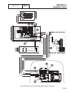
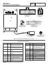
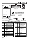
TERMINAL STRIP / INTERCONNECTION
TERMINAL
The terminals of this terminal strip are connected to
identically numbered terminals on a transfer switch
terminal board. The terminal board connects the
transfer switch to the circuit board.
The terminal board provides the following connection
points:
A. UTILITY 1 and UTILITY 2
1. Connect to identically marked terminals on a
transfer switch terminal board.
B. 23 and 15B
1. Connect to identically numbered terminals on
the terminal board of the transfer switch.
2. This circuit connects the circuit board to the
transfer relay coil in the transfer switch.
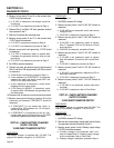
TERMINAL STRIP
0
N1
N2
15B
23
Figure 1. Terminal Strip
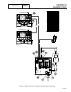
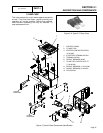
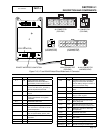
CIRCUIT BOARD
The circuit board controls all standby electric system
operations including (a) engine startup, (b) engine
running, (c) automatic transfer, (d) automatic retrans-
fer, and (e) engine shutdown. In addition, the circuit
board performs the following functions:
• Delivers“field boost”current tothe generator rotor
windings (see “Field Boost Circuit” in Section 2.2).
• Starts and “exercises” the generator once every
seven days.
• Providesautomaticengineshutdownintheeventof
low oil pressure, high oil temperature, overspeed,
no RPM sense, overcrank, or low battery.
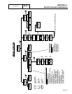
An 18-pin and a 4-pin connector are used to inter-
connect the circuit board with the various circuits of
the DC systems. Connector pin numbers, associated
wires and circuit functions are listed in the CHART on
the next page.
If the Utility sensing voltage drops below a preset
value, circuit board action will initiate automatic
generator startup and transfer to the “Standby”
source side.
The crank relay and fuel solenoid valve are energized
by circuit board action at the same time.
DIGITAL INPUT/OUTPUT FUNCTIONS:
Postion Digital Inputs Digital Outputs
1 Low Oil Pressure Not Used
2 High Temperature Not Used
3 Internal Use Not Used
4 Internal Use Not Used
5 Internal Use Fuel
6 Not Used Starter
7 Auto Ignition
8 Manual Transfer
*
DANGER: THE GENERATOR ENGINE WILL
CRANK AND START WHEN THE 7-DAY
EXERCISER SWITCH IS ACTUATED. THE UNIT
WILL ALSO CRANK AND START EVERY 7
DAYS THEREAFTER, ON THE DAY AND AT THE
TIME OF DAY THE SWITCH WAS ACTUATED.
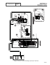
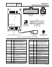
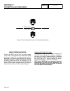
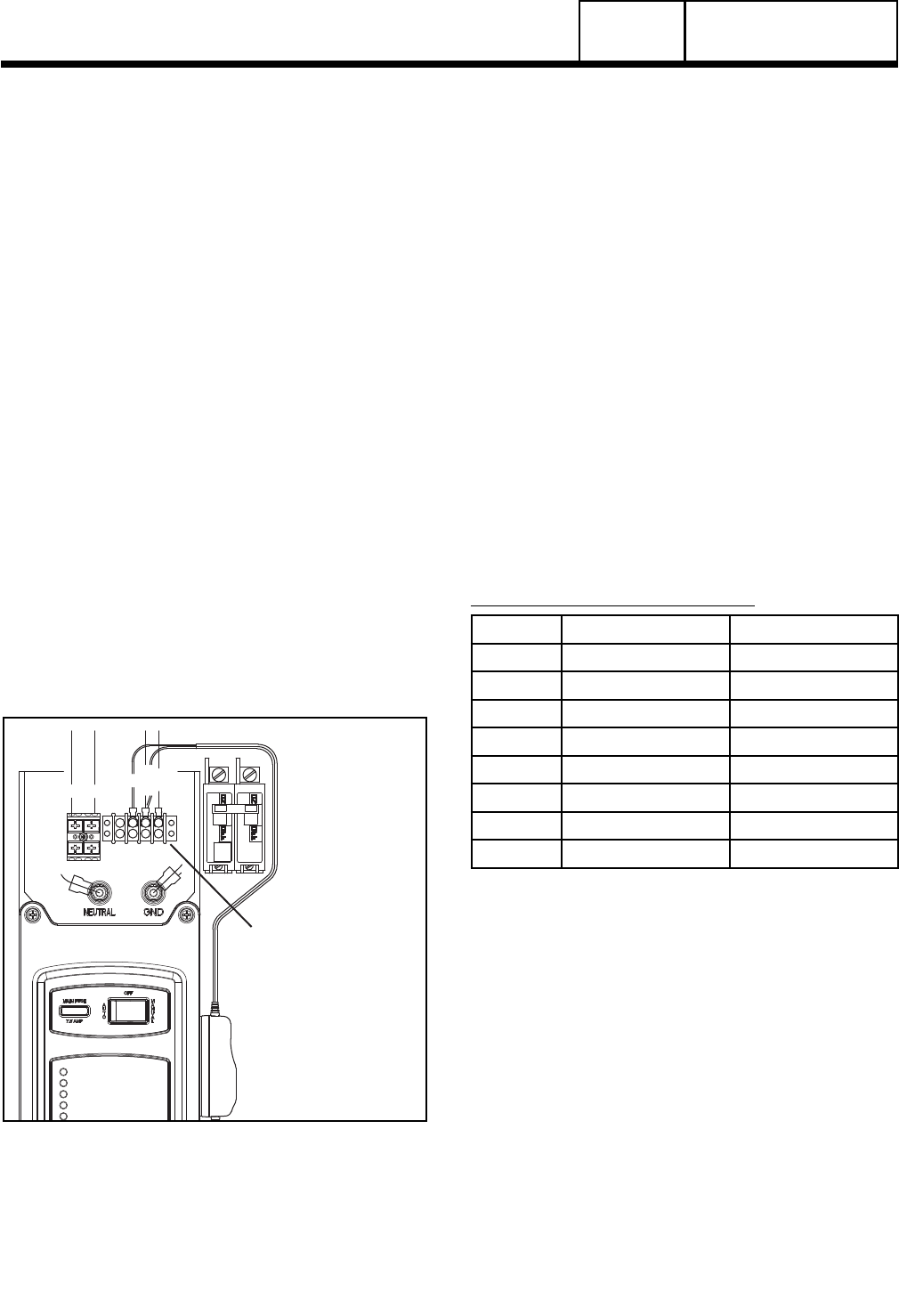
AUTO-OFF-MANUAL SWITCH
This 3-position switch permits the operator to (a)
select fully automatic operation, (b) start the generator
manually, or (c) stop the engine and prevent automatic
startup. Switch terminals are shown pictorially and
schematically in Figure 6, below.
Page 96
PART 4
DC CONTROL
SECTION 4.1
DESCRIPTION AND COMPONENTS