


AC GENERATORS
SECTION 2.1
DESCRIPTION & COMPONENTS
PART 2
Page 33
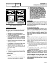
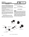
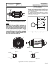
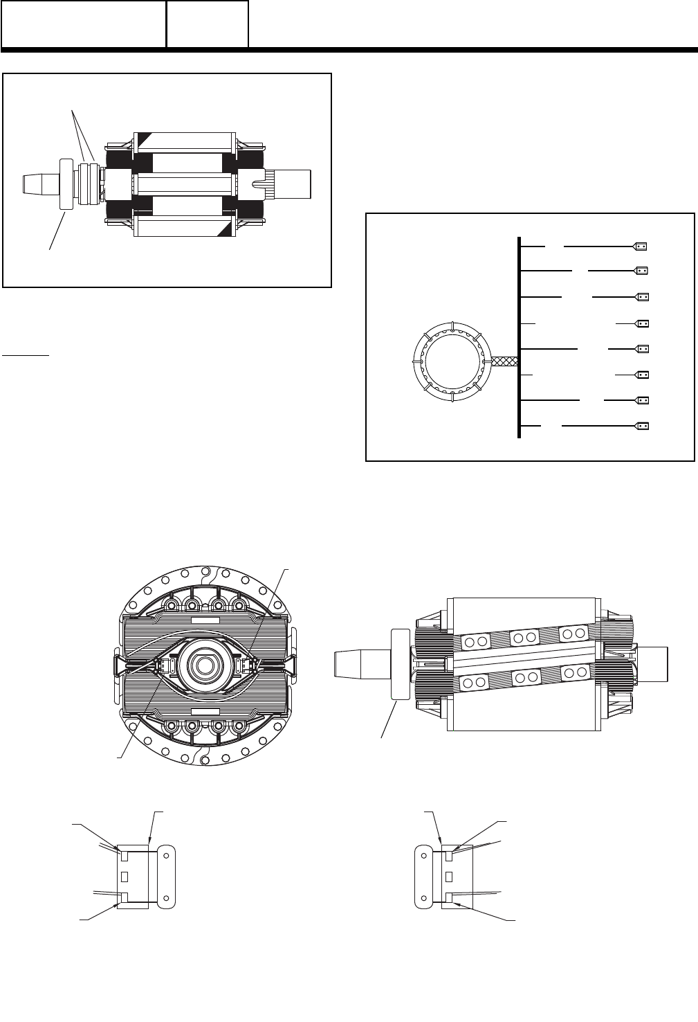
SLIP RINGS
BEARING
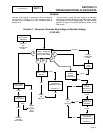
Figure 2. The 2-Pole Rotor Assembly 12-20 kW
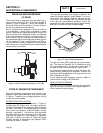
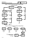
8/10KW:
Like the 12-20 kW rotor, the 8/10 kW 2-pole rotor must
be operated at 3600 rpm to supply a 60 Hertz AC fre-
quency. However, the 8/10kW rotor uses no slip rings.
As the rotor rotates in the generator voltage is induced
from the Excitation winding using a capacitor that is in
turn excited by the rotor. A continuous loop of charging
and discharging of the capacitor is maintained that
acts as a voltage regulation system. The rotor bearing
is pressed onto the end of the rotor shaft. The tapered
rotor shaft is mounted to a tapered crankshaft and is
held in place with a single through bolt.
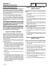
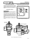
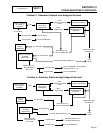
STATOR ASSEMBLY
The stator can houses and retains (a) dual AC power
windings, and (b) excitation winding. A total of six (6)
or eight (8) stator leads are brought out of the stator
can as shown in Figure 4.
The stator can is sandwiched between an engine
adapter and a rear bearing carrier. It is retained in that
position by four stator studs.
2
6
11P
44
33
22S (12-20 kW)
22P
11S
(12-20 kW)
Figure 4. Stator Assembly Leads
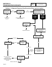
CATHODE
ANODE
DIODE B
DIODE B
CATHODE
DIODE A
COIL 2
ANODE
COIL 1
DIODE A
BEARING
Figure 3. The 2-Pole Rotor Assembly 8/10kW