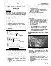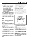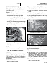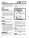
PROCEDURE:
1. Set a VOM to measure resistance.
2. Disconnect the J2 Connector from the controller.
3. Connect one meter test lead to the ground terminal.
Connect the other meter test lead to each of the follow-
ing J2 connector pin locations.
J2-11 Wire 56
8kW
If CONTINUITY was measured,
go to Step 4. Average nominal
resistance reading is 4 ohms:
Single Cylinder Starter Contactor
(SC) 4 ohms,
Choke Solenoid (CS) is 4 ohms.
10 kW - 20 kW
If CONTINUITY was measured,
go to Step 5.
Average nominal resistance reading
is 150-160 ohms.
V-twin Starter Contact Relay
(SCR): 150-160 ohms.
Choke Solenoid (CS) 4 ohms.
J2-3 Wire 14
8kW
If CONTINUITY was measured,
go to Step 6. Average nominal
resistance reading is 16 ohms:
Fuel Solenoid (FS): 16 ohms.
10kw
If CONTINUITY was measured,
go to Step 7. Average nominal
resistance reading is 16 ohms.
Fuel Solenoids (FS) 16 ohms,
(FS2) 7 ohms. Choke Solenoid
(CS) 4 ohms.
10 kW - 20 kW
If CONTINUITY was measured,
go to Step 8. Average nominal
resistance reading is 16 ohms.
Fuel Solenoid (FS) 16 ohms.
Choke Solenoid (CS) 4 ohms.
J2-12 Wire 4
10 kW - 20 kW
If RESISTANCE was measured,
go to Step 9.
For average nominal resistance
reading of the rotor, refer to the
front of the manual.
4. Disconnect Wire 56 and Wire 0 from the Starter
Contactor (SC). Disconnect the Choke Solenoid
(CS) connector.
a. Connect one meter test lead to the SC terminal
from which Wire 56 was removed. Connect the
other meter test lead to the ground terminal, 4
ohms should be measured. If zero resistance
was measured, replace the SC.
b. Connect one meter test lead to the CS connec-
tor Wire 56. Connect the other meter test lead
to the CS connector Wire 90. 4 ohms should
be measured. If zero resistance was measured,
replace the Choke Solenoid.
c. If coil resistance was measured in the Starter
Contactor, and Choke Solenoid Wire 56 is short-
ed to ground between the J2 Connector and SC
or CS, repair or replace the shorted wire.
5. Disconnect Wire 56 from the Starter Contactor Relay
(SCR). Disconnect the Choke Solenoid (CS) connector.
a. Connect one meter test lead to the SCR terminal
from which Wire 56 was removed. Connect the
other meter test lead to the ground terminal. 4
ohms should be measured. If zero resistance was
measured, replace the Starter Contactor Relay.
b. Connect one meter test lead to the CS connec-
tor Wire 56. Connect the other meter test lead
to the CS connector Wire 90. 4 ohms should
be measured. If zero resistance was measured,
replace the Choke Solenoid.
If coil resistance was measured in SCR and CS Wire
56 is shorted to ground between J2 connector and SC
or CS, repair or replace the shorted wire.
6. Disconnect Wire 14 from the Fuel Solenoid (FS).
a. Connect one meter test lead to the FS terminal
from which Wire 14 was removed. Connect the
other meter test lead to the ground terminal. 16
ohms should be measured. If zero resistance
was measured, replace the Fuel Solenoid.
b. If coil resistance was measured in FS Wire 14
is shorted to ground between J2 connector and
FS, repair or replace the shorted wire.
7. Disconnect Wire 14 from the Fuel Solenoid (FS), Fuel
Solenoid 2 (FS2), and Choke Solenoid (CS),
a. Connect one meter test lead to the FS terminal
from which Wire 14 was removed. Connect the
other meter test lead to the ground terminal. 16
ohms should be measured. If zero resistance
was measured, replace the Fuel Solenoid.
b. Connect one meter test lead to the FS2 termi-
nal from which Wire 14 was removed. Connect
the other meter test lead to the ground terminal.
7 ohms should be measured. If zero resistance
was measured, replace Fuel Solenoid 1.
c. At the CS connector, connect one meter test
lead to Wire 14 connect the other meter test
lead to Wire 90. 4 ohms should be measured.
If zero resistance was measured, replace the
Choke Solenoid.
Page 145
SECTION 4.4
DIAGNOSTIC TESTS
DC CONTROL
PART 4


