


GENERAL INFORMATION
SECTION 1.5
TESTING, CLEANING AND DRYING
PART 1
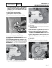
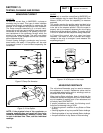
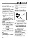
HI-POT TESTER:
A “Hi-Pot” tester is shown in Figure 7. The model
shown is only one of many that are commercially
available. The tester shown is equipped with a voltage
selector switch that permits the power supply voltage
to be selected. It also mounts a breakdown lamp that
will illuminate to indicate an insulation breakdown dur-
ing the test.
STATOR INSULATION RESISTANCE TEST
(12-20 KW)
GENERAL:
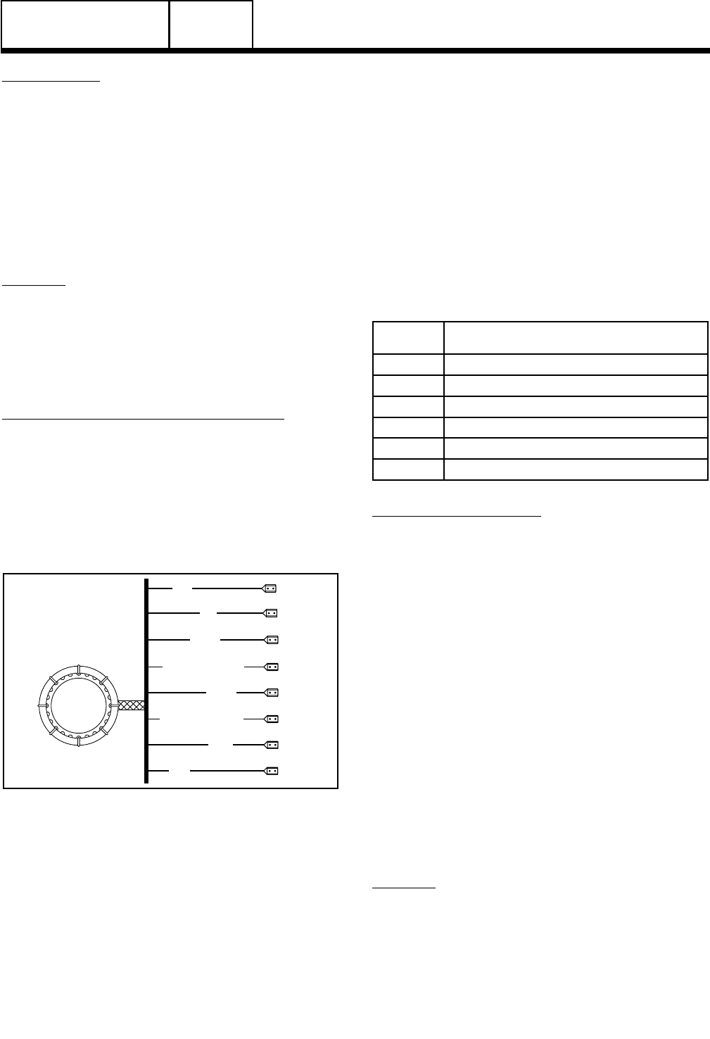
Units with air-cooled engine are equipped with (a)
dual stator AC power windings, and (b) excitation or
DPE winding. Insulation tests of the stator consist of
(a) testing all windings to ground, (b) testing between
isolated windings, and (c) testing between parallel
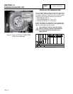
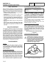
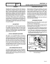
windings. Figure 8 is a pictorial representation of the
various stator leads on units with air-cooled engines.
TESTING ALL STATOR WINDINGS TO GROUND:
1. Disconnect stator output leads 11 and 44 from the gen-
erator main line circuit breaker.
2. Remove stator output leads 22 and 33 from the neutral
connection and separate the two leads.
3. Disconnect Wires 11 and 22 from Voltage Regulator.
Ensure these wires are not touching any other compo-
nents on the generator.
2
6
11P
44
33
22S (12-20 kW)
22P
11S
(12-20 kW)
Figure 8. Stator Winding Leads
4. Connect the terminal ends of Wires 11, 22, 33 and 44
together. Make sure the wire ends are not touching any
part of the generator frame or any terminal.
5. Connect the red test probe of the Hi-Pot tester to the
joined terminal ends of stator leads 11, 22, 33 and 44.
Connect the black tester lead to a clean frame ground
on the stator can. With tester leads connected in this
manner, proceed as follows:
a. Turn the Hi-Pot tester switch OFF.
b. Plug the tester cord into a 120 volt AC wall
socket and set its voltage selector switch to
“1500 volts”.
c. Turn the tester switch ON and observe the
breakdown lamp on tester. DO NOT APPLY
VOLTAGE LONGER THAN 1 SECOND. After
one (1) second, turn the tester switch OFF.
If the breakdown lamp comes on during the one-sec-
ond test, the stator should be cleaned and dried. After
cleaning and drying, repeat the insulation test. If, after
cleaning and drying, the stator fails the second test,
the stator assembly should be replaced.
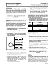
6. Proceed to the Voltage Regulator. Each winding will be
individually tested for a short to ground. Refer to Steps
5a-5c and perform the same test on the following wires:
Wire
Number
Winding
22S Sense Lead Power
11S Sense Lead Power
6 Excitation
2 Excitation
0 Ground
4 Positive to Brush Ground
TEST BETWEEN WINDINGS:
1. Disconnect Stator Output Leads 11 and 44 from the
generator main line circuit breaker.
2. Remove Stator Output Leads 22 and 33 from the neutral
connection and separate the two leads.
3. Disconnect Wires 11, 22, 2, and 6 from Voltage
Regulator. Ensure these wires are not touching any
other components on the generator.
4. Connect the red tester probe to Wire 2. Connect the
black tester probe to Stator Lead 11. Refer to Steps 5a
through 5c of “TESTING ALL STATOR WINDINGS TO
GROUND” on previous page.
5. Repeat Step 4 between Wire 2 and Stator Lead 33.
6. Repeat Step 4 between Stator Lead 11 and Stator Lead 33.
STATOR INSULATION RESISTANCE TEST
(8-10 KW)
GENERAL:
Units with air-cooled engine are equipped with (a)
dual stator AC power windings, and (b) excitation or
DPE winding. Insulation tests of the stator consist of
(a) testing all windings to ground, (b) testing between
isolated windings, and (c) testing between parallel
windings. Figure 8 is a pictorial representation of the
various stator leads on units with air-cooled engines.
Page 23