


Page 142
a. Disconnect the J1 Connector from the printed
circuit board.
b. Connect one test lead to Wire 86 (disconnected
from LOP). Connect the other test lead to Pin
Location 4 (Wire 86) of the J1 Connector at the
Circuit Board (for all models). CONTINUITY
should be measured. If CONTINUITY is not
measured, repair or replace Wire 86 between
the LOP switch and the J1 Connector.
c. Connect one test lead to Wire 0 ( disconnected
from LOP). Connect the other test lead to a clean
frame ground. CONTINUITY should be measured.
If CONTINUITY is NOT measured repair or replace
Wire 0 between the LOP and the ground terminal
connection on the engine mount.
7. If the LOP switch tests good in Step 5 and oil pressure
is good in Step 4 but the unit still shuts down with a LOP
fault, check Wire 86 for a short to ground. Set a VOM to
measure resistance. Disconnect the J1 Connector from
the circuit board. Remove Wire 86 from the LOP switch.
Connect one test lead to Wire 86. Connect the other
test lead to a clean frame ground. INFINITY should be
measured. If CONTINUITY is measured, repair or replace
Wire 86 between the LOP switch and the J1 Connector.
RESULTS:
1. Replace switch if it fails the test.
TEST 76 – CHECK HIGH OIL TEMPERATURE
SWITCH
DISCUSSION:
If the temperature switch contacts have failed in a closed
position, the engine will fault out on “OVERTEMP”. If the
unit is in an overheated condition, the switch contacts will
close at 293° F. This will normally occur from inadequate
airflow through the generator.
PROCEDURE:
1. Verify that the engine has cooled down (engine block
is cool to the touch). This will allow the contacts in the
High Oil Temperature Switch to close.
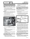
2. Check the installation and area surrounding the generator.
There should be at least three feet of clear area around
the entire unit. Make sure that there are no obstructions
preventing incoming and outgoing air.
3. Disconnect Wire 85 and Wire 0 from the High Oil
Temperature Switch.
4. Set a VOM to measure resistance. Connect the test
leads across the switch terminals. The meter should
read INFINITY.
5. If the switch tested good in Step 4, and a true overtem-
perature condition has not occurred, check Wire 85 for a
short to ground. Remove J1 Connector from the circuit
board. Set the VOM to measure resistance. Connect
one test lead to Wire 85 (disconnected from High Oil
Temperature Switch). Connect the other test lead to a
clean frame ground. INFINITY should be measured.
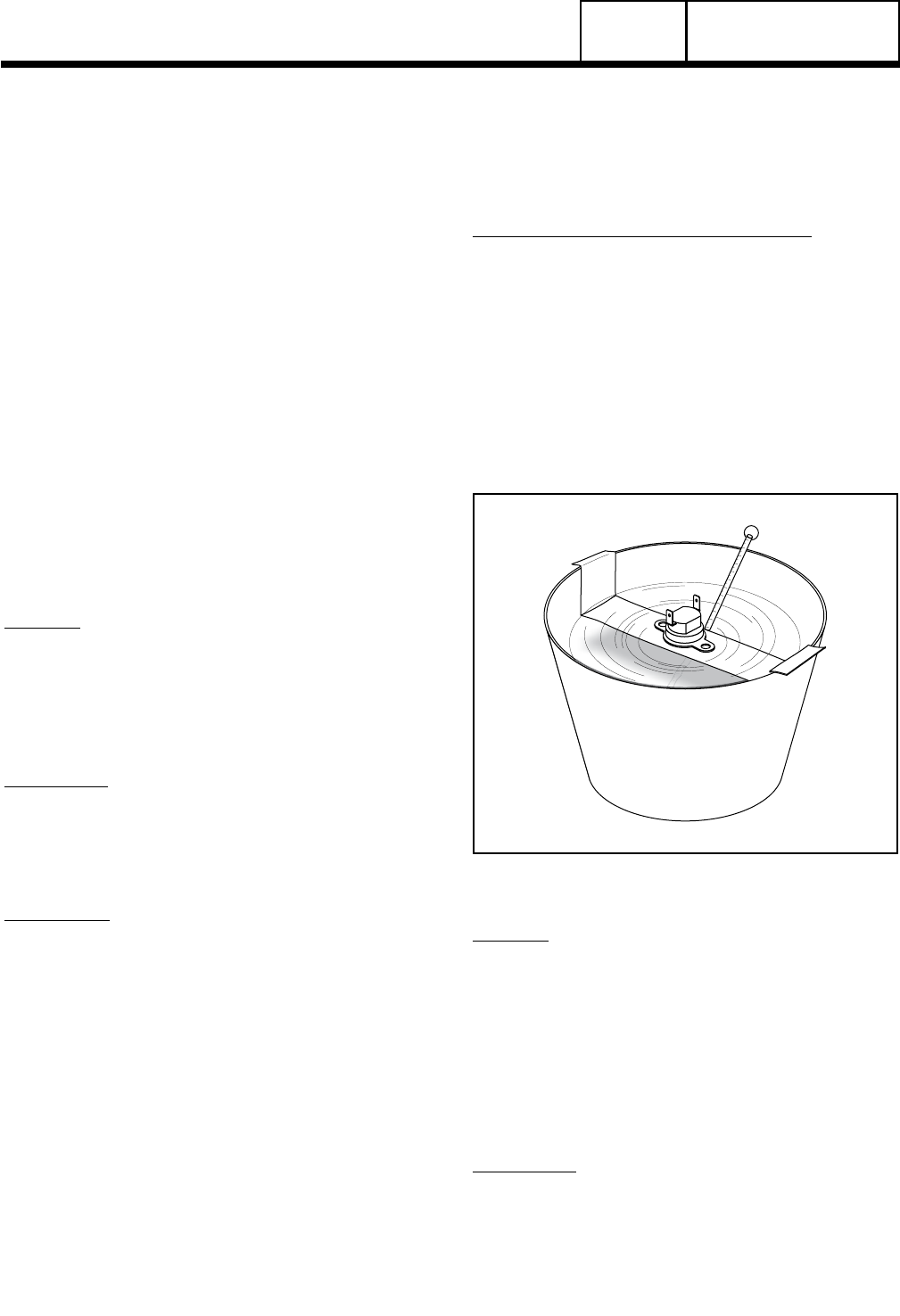
TESTING HIGH OIL TEMPERATURE SWITCH:
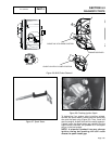
6. Remove the High Oil Temperature Switch.
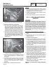
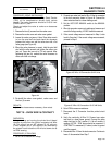
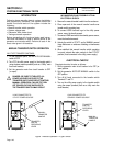
7. Immerse the sensing tip of the switch in oil as shown in
Figure 43, along with a suitable thermometer.
8. Set a VOM to measure resistance. Then, connect the
VOM test leads across the switch terminal and the
switch body. The meter should read INFINITY.
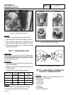
9. Heat the oil in the container. When the thermometer
reads approximately 283°-305° F. (139°-151° C.), the
VOM should indicate CONTINUITY.
Figure 43. Testing the Oil Temperature Switch
RESULTS:
1. If the switch fails Step 4, or Steps 8-9, replace the
switch.
2. If INFINITY was NOT measured in Step 5, repair or
replace Wire 85 between the Circuit Board and the High
Oil Temperature Switch.
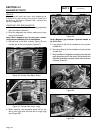
TEST 77 – CHECK AND ADJUST VALVES
DISCUSSION:
Improperly adjusted valves can cause various engine
related problems including, but not limited to, hard
starting, rough running and lack of power. The valve
adjustment procedure for both the single cylinder and
the V-twin engines is the same.
PART 4
DC CONTROL
SECTION 4.4
DIAGNOSTIC TESTS