


AC GENERATORS
SECTION 2.4
DIAGNOSTIC TESTS
INTRODUCTION
This section is provided to familiarize the service
technician with acceptable procedures for the test-
ing and evaluation of various problems that could be
encountered on standby generators with air-cooled
engine. Use this section of the manual in conjunction
with Section 2.3, “Troubleshooting Flow Charts”. The
numbered tests in this section correspond with those
of Section 2.3.
Test procedures in this section do not require the use
of specialized test equipment, meters or tools. Most
tests can be performed with an inexpensive volt-
ohm-milliammeter (VOM). An AC frequency meter is
required, where frequency readings must be taken. A
clamp-on ammeter may be used to measure AC loads
on the generator.
Testing and troubleshooting methods covered in this
section are not exhaustive. We have not attempted to
discuss, evaluate and advise the home standby ser-
vice trade of all conceivable ways in which service and
trouble diagnosis might be performed. We have not
undertaken any such broad evaluation. Accordingly,
anyone who uses a test method not recommended
herein must first satisfy himself that the procedure or
method he has selected will jeopardize neither his nor
the product’s safety.
SAFETY
Service personnel who work on this equipment must
be made aware of the dangers of such equipment.
Extremely high and dangerous voltages are present
that can kill or cause serious injury. Gaseous fuels are
highly explosive and can be ignited by the slightest
spark. Engine exhaust gases contain deadly carbon
monoxide gas that can cause unconsciousness or
even death. Contact with moving parts can cause seri-
ous injury. The list of hazards is seemingly endless.
When working on this equipment, use common
sense and remain alert at all times. Never work on
this equipment while you are physically or mentally
fatigued. If you don’t understand a component, device
or system, do not work on it.
TEST 1 – CHECK MAIN CIRCUIT BREAKER
DISCUSSION:
Often the most obvious cause of a problem is over-
looked. If the generator main line circuit breaker is set
to OFF or “Open”, no electrical power will be supplied
to electrical loads. If loads are not receiving power,
perhaps the main circuit breaker is open or has failed.
PROCEDURE:
The generator main circuit breaker is located on the
control panel. If loads are not receiving power, make
sure the breaker is set to “On” or “Closed”.
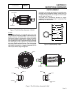
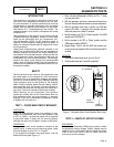
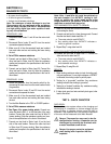
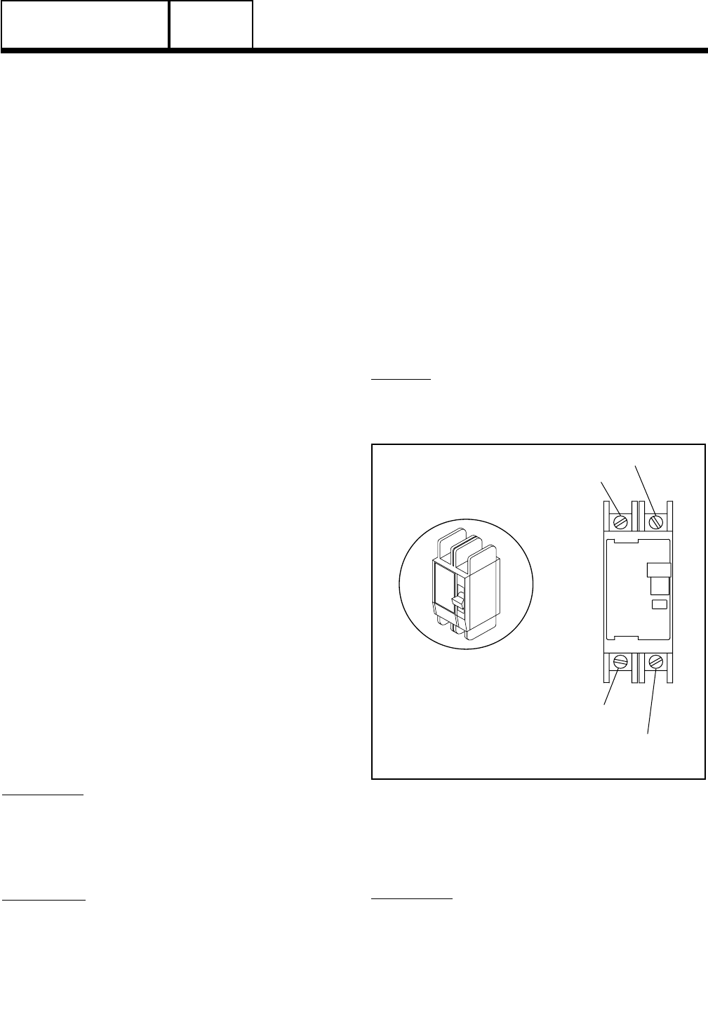
If you suspect the breaker may have failed, it can be
tested as follows (see Figure 1):
1. Set a volt-ohm-milliammeter (VOM) to its “R x 1” scale
and zero the meter.
2. With the generator shut down, disconnect all wires from
the main circuit breaker terminals, to prevent interaction.
3. With the generator shut down, connect one VOM test
probe to the Wire 11 terminal of the breaker and the
other test probe to the Wire E1 terminal.
4. Set the breaker to its “On” or “Closed” position. The VOM
should read CONTINUITY.
5. Set the breaker to its OFF or “Open” position and the
VOM should indicate INFINITY.
6. Repeat Steps 4 and 5 with the VOM test probes con-
nected across the breaker’s Wire 44 terminal and the E2
terminal.
RESULTS:
1. If the circuit breaker tests good, go on to Test 2.
2. If the breaker tests bad, it should be replaced.
O
F
F
WIRE 11
TERMINAL
E1 TERMINAL
E2 TERMINAL
WIRE 44
TERMINAL
Figure 1. Generator Main Circuit Breaker Test Points
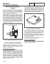
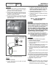
TEST 2 – CHECK AC OUTPUT VOLTAGE
DISCUSSION:
A volt-ohm-milliammeter (VOM) may be used to check
the generator output voltage. Output voltage may be
checked at the unit’s main circuit breaker terminals.
Refer to the unit’s DATA PLATE for rated line-to-line
and line-to-neutral voltages.
PART 2
Page 41