


Page 130
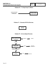
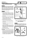
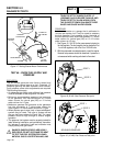
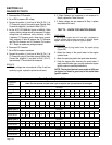
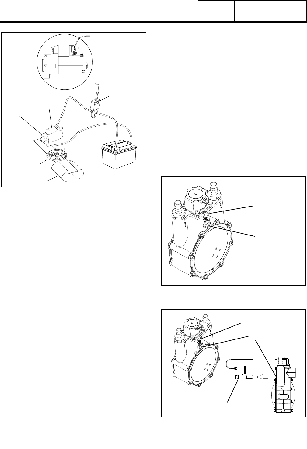
STARTER
CONTACTOR
STARTER
MOTOR
TACHOMETER
12 VOLT
BATTERY
CLAMP ON
AMP METER
VISE
Figure 17. Testing Starter Motor Performance
TEST 66 – CHECK FUEL SUPPLY AND
PRESSURE
DISCUSSION:
The air-cooled generator was factory tested and
adjusted using natural gas as a fuel. If desired, LP
(propane) gas may be used. However, when convert-
ing to propane, some minor adjustments are required.
The following facts apply:
• Anadequategassupplyandsufficientfuelpressure
must be available or the engine will not start.
• Minimum recommended gaseous fuel pressure
at the generator fuel inlet connection is 5 inches
water column for natural gas (NG) or 10 inches
water column for LP gas.
• Maximum gaseous fuel pressure at the generator
fuel inlet connection is 7 inches water column for
natural gas or 12 inches water column for LP gas.
• Whenpropanegasisused,onlya“vaporwithdrawal”
system may be used. This type of system utilizes
the gas that forms above the liquid fuel. The vapor
pressure must be high enough to ensure engine
operation.
• Thegaseousfuelsystemmustbeproperlytestedfor
leaks following installation and periodically thereafter.
No leakage is permitted. Leak test methods must
comply strictly with gas codes.
*
DANGER: GASEOUS FUELS ARE HIGHLY
EXPLOSIVE. DO NOT USE FLAME OR HEAT
TO TEST THE FUEL SYSTEM FOR LEAKS.
NATURAL GAS IS LIGHTER THAN AIR, AND
TENDS TO SETTLE IN HIGH PLACES. LP
(PROPANE) GAS IS HEAVIER THAN AIR, AND
TENDS TO SETTLE IN LOW AREAS. EVEN
THE SLIGHTEST SPARK CAN IGNITE THESE
GASES AND CAUSE AN EXPLOSION.
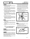
PROCEDURE:
A water manometer or a gauge that is calibrated in
“ounces per square inch” may be used to measure
the fuel pressure. Fuel pressure at the inlet side of
the fuel solenoid valve should be between 5-7 inches
water column for natural gas (NG) or 10-12 inches
water column for LP gas.
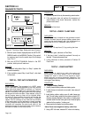
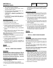
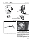
1. See Figures 18, 19 or 20 for the gas pressure test point on
the fuel regulator. The fuel pressure can be checked at Port
1 on all fuel regulators, and at Port 3 on 12-20 kW units.
2. With the manometer connected properly, crank the engine.
Nominal fuel pressure should be measured. If pressure is
not measured while cranking refer back to flow chart.
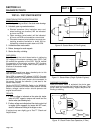
PORT 1
PORT 2
Figure 18 (8 kW) Gas Pressure Test point
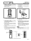
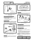
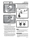
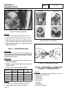
PORT 1
PORT 2
SOLENOID REMOVED
Figure 19 (10 kW) Gas Pressure Test point
PART 4
DC CONTROL
SECTION 4.4
DIAGNOSTIC TESTS