


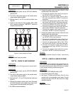
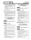
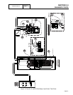

2. Test for utility source line-to-line voltage across Terminal
Lugs N1 and N2 (see Figure 1). Normal utility source
voltage should be indicated.
RESULTS:
1. If low or no voltage is indicated, find the cause of the
problem and correct.
2. If normal utility source voltage is indicated, refer to
Flow Chart.
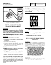
TEST 40 – CHECK BATTERY CHARGER
SUPPLY VOLTAGE
“PRE-WIRE LOAD CENTER”
DISCUSSION:
The battery charger is supplied with 120 VAC. The
output of the battery charger is 13.4 VDC / 2.5A.
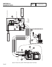
PROCEDURE:
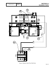
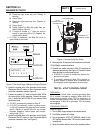
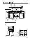
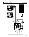
Refer to Figure 11.
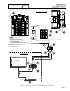
1. Set VOM to measure AC voltage.
2. Measure across points A and B. 240 VAC should be
measured.
a. If 240 VAC is not measured, verify load source
voltage.
b. If 240 VAC is measured go to Step 3.
3. Measure across points A and C. 240 VAC should be
measured.
a. If 240 VAC is not measured, repair or replace
Wire T1.
b. If 240VAC is measured, proceed to Step 4.
4. Measure across points A and D. 240 VAC should be
measured.
a. If 240 VAC is not measured, replace fuse F3.
b. If 240VAC is measured, proceed to Step 5.
5. Remove Fuse F3. Measure across points D and C.
120 VAC should be measured.
a. If 120 VAC is not measured, verify neutral wire
is connected at point E. If good, replace battery
charger, then retest.
b. If 120VAC is measured, refer to Flow Chart.
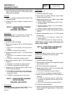
TEST 41 – CHECK BATTERY CHARGER
OUTPUT VOLTAGE
“PRE-WIRE LOAD CENTER”
DISCUSSION:
The battery charger is supplied with 120VAC. The out-
put of the battery charger is 13.4 VDC / 2.5A.
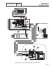
PROCEDURE:
Refer to Figure 11.
1. Set VOM to measure DC voltage.
2. Remove Wire 0 and Wire 15B from transfer switch
terminal strip points F and G.
3. Measure across points H and I. Battery supply voltage
(12 VDC) should be measured.
a. If battery voltage is not measured, wait 5 minutes
and repeat Step 3.
b. If battery supply voltage is still not available,
refer to Flow Chart.
c. If battery voltage is measured, proceed to Step 4.
4. Reconnect Wire 0 and Wire 15B previously removed
in Step 2.
5. Measure across points H and I. 13.4 VDC should
be measured.
a. If 13.4 VDC is not measured, replace the
battery charger
b. If 13.4 VDC is measured, the charger is working.
*NOTE: Battery charger voltage will be higher than
battery supply voltage.
TEST 42 – CHECK WIRE 0 AND WIRE15B
“PRE-WIRE LOAD CENTER”
DISCUSSION:
In order for the battery charger to function, battery supply
voltage must be available to the battery charger.
PROCEDURE:
Refer to Figure 11.
1. Set VOM to measure DC voltage.
2. Disconnect Wire 0 and Wire 15B from generator terminal
strips, locations J and K.
3. Wait five (5) minutes after removing wires.
4. Measure across points L and M on the terminal strip.
12 VDC should be measured.
a. If 12 VDC is measured, proceed to Step 6.
b. If 12 VDC is not measured, proceed to Step 5.
5. Measure across points M and N. 12 VDC should be
measured.
a. If 12 VDC is measured, repair or replace Wire
0 between the generator terminal strip and the
ground lug.
b. If 12 VDC is not measured, proceed to Step 8.
6. Set VOM to measure resistance.
7. Connect the meter test leads across the disconnected
Wire 0 and Wire 15B. Approximately 115 Ohms should
be measured.
PART 3
TRANSFER SWITCH
SECTION 3.4
DIAGNOSTIC TESTS
Page 86