


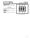
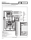
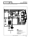
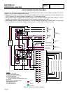
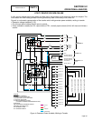
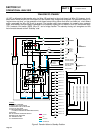
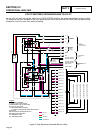
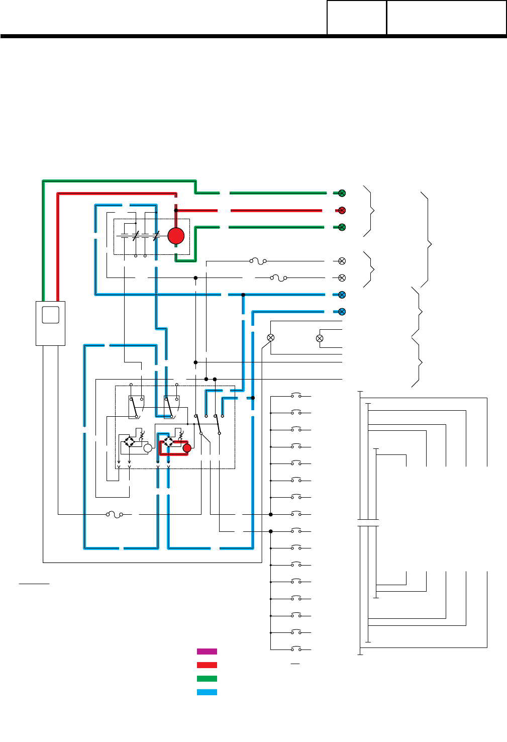
TRANSFER TO STANDBY
12 VDC is delivered to the transfer relay via Wire 15B and back to the circuit board via Wire 23. However, circuit
board action holds the Wire 23 circuit open and the transfer relay remains de-energized. On generator startup, an
“engine warm-up timer” on the generator circuit board starts timing. When that timer has timed out, circuit board
action completes the Wire 23 circuit to ground. The transfer relay then energizes, its normally open contacts
close, and standby source voltage is delivered to the standby closing coil via Wires E1 and E2, the transfer relay
(TR1) contacts, limit switch (SW3), Wire “B”, and a bridge rectifier. The standby closing coil energizes and the
main contacts actuate to their “Standby” side.
Page 64
NEUTRAL
CONNECTION
SWITCH
SW3
NO
C1
COM
SW2
VR1
NC NC
COM
C2
VR2
NO
TR1
15B
23
1
7
4
7 9
3 6
9
F2
CIRCUIT 10
BLACK (MAIN 1)
CONTROL
TRANSFER
RED (MAIN 2)
NEUTRAL (WHITE)
NEUTRAL (WHITE)
23
0
F1
N2
N1
15B
23
BLACK
RED
N2
N1
15B
240VAC TO
TO GENERATOR
OUTPUT
PANEL
MAIN DISTRIBUTION
T1
T2
T1 T2
E2
E2
E2
E2
E1
E1
N1A
N1A
N2A
N2A
B
B
B
B
B
E1
E1
E1
N1AN1A
N1A
15B
23
E1
E2
205
205
126
126
E2
N1A
N2A
N2A
A
N2A
240VAC
OUTPUT
GENERATOR
TS TO
CONTROL PANEL
A
B
SW1
LC
CIRCUIT 9
CIRCUIT 6
CIRCUIT 5
CIRCUIT 2
CIRCUIT 1
CIRCUIT 3
CIRCUIT 4
CIRCUIT 7
CIRCUIT 8
CIRCUIT 11
CIRCUIT 12
CIRCUIT 13
CIRCUIT 14
CIRCUIT 16
CIRCUIT 15
14 CIRCUIT LOAD CENTER
12 CIRCUIT LOAD CENTER
10 CIRCUIT LOAD CENTER
8 CIRCUIT LOAD CENTER
T1
T1
F3
0
WIRE
-
WIRE
BLK
+
RED
BC
0
16 CIRCUIT LOAD CENTER
BC-BATTERY CHARGER
N-NEUTRAL
TR1-TRANSFER RELAY
SW2,SW3-LIMIT SWITCHES
TB1-TERMINAL STRIP
F1,F2,F3-5A, 600V FUSE
C1-UTILITY COIL & RECTIFIER
C2-GENERATOR COIL & RECTIFIER
SW1-AUTOMATIC TRANSFER SWITCH
(16 CIRCUIT SHOWN FOR REFERENCE ONLY)
LC-CIRCUIT BREAKER (LOADS)
LEGEND
SENSING
UTILITY
INSIDE
GROUND (GREEN)
GROUND (GREEN)
UTILITY
GENERATOR
GROUND
DC
Figure 5. Transfer Action to Standby Position
PART 3
TRANSFER SWITCH
SECTION 3.2
OPERATIONAL ANALYSIS