


GENERAL INFORMATION
SECTION 1.5
TESTING, CLEANING AND DRYING
Component testing may require a specific resis-
tance value or a test for INFINITY or CONTINUITY.
Infinity is an OPEN condition between two electrical
points, which would read as no resistance on a VOM.
Continuity is a closed condition between two electrical
points, which would be indicated as very low resis-
tance or “ZERO” on a VOM.
ELECTRICAL UNITS
AMPERE:
The rate of electron flow in a circuit is represented
by the AMPERE. The ampere is the number of elec-
trons flowing past a given point at a given time. One
AMPERE is equal to just slightly more than six thou-
sand million billion electrons per second.
With alternating current (AC), the electrons flow first
in one direction, then reverse and move in the oppo-
site direction. They will repeat this cycle at regular
intervals. A wave diagram, called a “sine wave” shows
that current goes from zero to maximum positive
value, then reverses and goes from zero to maximum
negative value. Two reversals of current flow is called
a cycle. The number of cycles per second is called
frequency and is usually stated in “Hertz”.
VOLT:
The VOLT is the unit used to measure electrical
PRESSURE, or the difference in electrical potential
that causes electrons to flow. Very few electrons will
flow when voltage is weak. More electrons will flow as
voltage becomes stronger. VOLTAGE may be consid-
ered to be a state of unbalance and current flow as
an attempt to regain balance. One volt is the amount
of EMF that will cause a current of 1 ampere to flow
through 1 ohm of resistance.
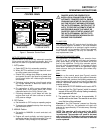
-
+
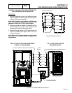
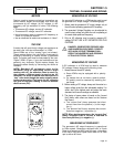
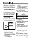
AMPERE - Unit measuring rate of
current flow (number of electrons
past a given point)
OHM - Unit measuring resistance
or opposition to flow
VOLT - Unit measuring force or
difference in potential
causing current flow
Conductor of a
Circuit
Figure 5. Electrical Units
OHM:
The OHM is the unit of RESISTANCE. In every circuit
there is a natural resistance or opposition to the flow
of electrons. When an EMF is applied to a complete
circuit, the electrons are forced to flow in a single
direction rather than their free or orbiting pattern. The
resistance of a conductor depends on (a) its physical
makeup, (b) its cross-sectional area, (c) its length,
and (d) its temperature. As the conductor’s tempera-
ture increases, its resistance increases in direct pro-
portion. One (1) ohm of resistance will permit one (1)
ampere of current to flow when one (1) volt of electro-
motive force (EMF) is applied.
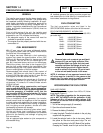
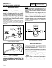
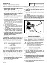
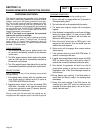
OHM’S LAW
A definite and exact relationship exists between
VOLTS, OHMS and AMPERES. The value of one can
be calculated when the value of the other two are
known. Ohm’s Law states that in any circuit the current
will increase when voltage increases but resistance
remains the same, and current will decrease when
resistance Increases and voltage remains the same.
VOLTS
(E)
AMPS
(I)
OHMS
(R)
Figure 6. Ohm’s Law
If AMPERES is unknown while VOLTS and OHMS are
known, use the following formula:
AMPERES =
VOLTS
OHMS
If VOLTS is unknown while AMPERES and OHMS are
known, use the following formula:
VOLTS = AMPERES x OHMS
If OHMS is unknown but VOLTS and AMPERES are
known, use the following:
OHMS
=
VOLTS
AMPERES
PART 1
Page 21