


TRANSFER SWITCH
SECTION 3.4
DIAGNOSTIC TESTS
PART 3
Page 77
13. Set VOM to measure DC voltage.
14. Connect the (-) negative meter test lead to Wire 0 at the
terminal strip in the generator. Connect the (+) positive
meter test lead to Wire 23 at the terminal strip in the
generator. 12 VDC should be measured.
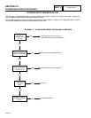
15. Place generator AUTO-OFF-MANUAL switch to the
AUTO position. Turn off utility power supply to the
transfer switch, simulating a utility failure. After the
generator starts 10 seconds should elapse before
transfer occurs. At that time the VOM DC voltage
should drop to zero. This indicates the PCB energized
the transfer relay.
a. If DC voltage drops to zero, refer to Flow Chart.
b. If DC voltage remains constant at 12 VDC, pro-
ceed to Step 16.
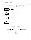
16. With the generator running and utility off, ground Wire 23
in the control panel at the terminal strip. If transfer relay
energizes and or transfer occurs, replace the PCB.
17. Set VOM to measure DC voltage.
18. Connect the negative (-) test lead to the ground lug in
the transfer switch. Connect the positive (+) test lead to
Wire 15B at the terminal strip in the transfer switch.
a. If voltage is present repair or replace Wire 0
between transfer switch and generator ground
lug.
b. If voltage is not present proceed to Step 19.
19. Connect the negative (-) test lead to the ground lug in
the generator control panel. Connect the positive (+) test
lead to Wire 15B at the terminal strip in the generator
control panel.
a. If voltage is present, repair Wire 15B between
generator terminal strip and transfer switch
terminal strip.
b. If voltage is not present, proceed to Step 20.
20. Remove the J2 connector from the circuit board.
21. Set VOM to measure ohms. Connect one meter test lead
to Wire 15B at the control panel terminal strip. Connect
the other meter test lead to Wire 15B Pin Location J2-8.
Continuity should be measured.
a. If continuity is not measured, repair pin connection
and or Wire 15B between the J2 connector and
terminal strip.
b. If continuity is measured proceed to Step 22.
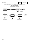
22. Remove the 7.5A fuse.
23. Reconnect J2 connector.
24. Install the 7.5A fuse.
25. Disconnect Wire 15B from the generator terminal strip.
26. Set VOM to measure DC voltage.
*
Caution: After installing the 7.5A fuse and dis-
connecting Wire 15B from the generator termi-
nal strip, wait 5 minutes before proceeding.
27. Connect one meter test lead to Wire 15B. Connect the other
meter test lead to Wire 0. 12 VDC should be measured.
a. If 12 VDC is not measured, replace the printed
circuit board.
b. If 12 VDC is measured, a short exists on Wire
15B or the transfer relay is shorted. Repair or
replace as needed.
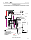
TEST 29 – TEST TRANSFER RELAY TR
DISCUSSION:
In automatic operating mode, the transfer relay must
be energized by circuit board action or standby source
power will not be available to the standby closing coil.
Without standby source power, the closing coil will
remain de-energized and transfer to “Standby” will not
occur. This test will determine if the transfer relay is
functioning normally.
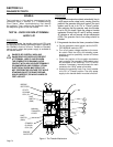
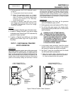
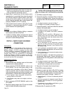
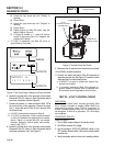
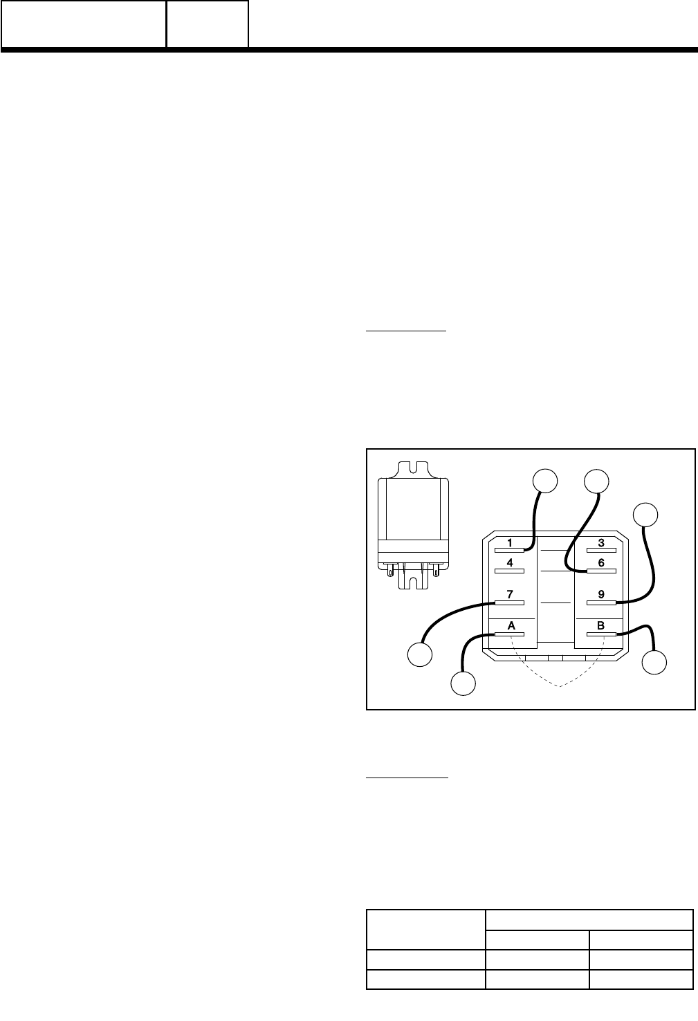
15B
COIL NOMINAL RESISTANCE = 120 Ohms
N1A
126
205
E1
23
Figure 3. Transfer Relay Test Points
PROCEDURE:
1. See Figure 3. Disconnect all wires from the transfer
relay, to prevent interaction.
2. Set a VOM to its “R x 1” scale and zero the meter.
3. Connect the VOM test leads across Relay Terminals 6
and 9 with the relay de-energized. The VOM should read
INFINITY.
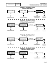
CONNECT VOM TEST
LEADS ACROSS
DESIRED METER READING
ENERGIZED DE-ENERGIZED
Terminals 6 and 9 Continuity Infinity
Terminals 1 and 7 Infinity Continuity