


AC GENERATORS
SECTION 2.4
DIAGNOSTIC TESTS
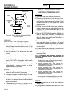
Connect the other meter test lead to Wire 4 (still dis-
connected from previous tests). Measure and record
static rotor amp draw.
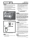
13. Set the AUTO-OFF-MANUAL switch to the MANUAL
position. Once the engine starts, repeat Step 12.
Measure and record running rotor amp draw with the
engine running.
14. Set the AUTO-OFF-MANUAL switch to OFF. Reconnect
Wire 4 to the voltage regulator.
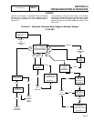
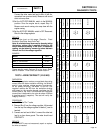
RESULTS:
Refer to the chart on this page: “Results - Fixed
Excitation Test/Rotor Amp Draw Test”.
Note: A calculated amp draw can be done by taking
the battery voltage that is applied divided by the
actual resistance reading of the rotor. A resistance
reading can be taken by measuring ohms between
Wires 4 and 0 at the voltage regulator.
EXAMPLE:
MODEL 5517
WIRE 2 & 6 VOLTAGE 87 VAC
WIRE 11 & 22 VOLTAGE 31 VAC
STATIC ROTOR AMP DRAW 1.0 AMP
RUNNING ROTOR AMP DRAW 1.0 AMP
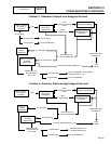
These results match Column B in the chart. Refer
back to Problem 1 Flow Chart and follow Letter B.
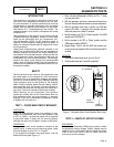
TEST 5 – WIRE CONTINUITY (12-20 KW)
DISCUSSION:
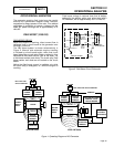
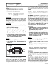
The voltage regulator receives unregulated alternating
current from the stator excitation winding, via Wires 2
and 6. It also receives voltage sensing from the sta-
tor AC power windings, via Wires 11 and 22. The
regulator rectifies the AC from the excitation winding
and based on the sensing signals, regulates the DC
current flow to the rotor. The rectified and regulated
current flow is delivered to the rotor brushes via Wires
4 (positive) and 0 (negative). This test will verify the
integrity of Wire 0.
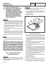
PROCEDURE:
1. Set VOM to its “R x 1” scale.
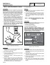
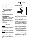
2. Remove Wire 0 from the voltage regulator, 4th terminal
from the top. Also voltage regulator is labeled (-) next to
terminal.
3. Connect one test lead to Wire 0, connect the other test
lead to a clean frame ground. The meter should read
CONTINUITY.
RESULTS:
If CONTINUITY was not measured, repair or replace
the wire as needed.
PART 2
Page 43
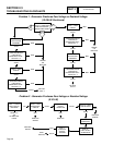
TEST 4 Results - Fixed Excitation Test/Rotor Amp Draw Test (12-20 kW)
Results: (Model #) A B C D E F G H
Voltage Results
Wire 2 & 6
ALL Above 60 VAC Above 60 VAC Below 60 VAC
Zero or Residual
Volts
Below 60 VAC Below 60 VAC Above 60 VAC Below 60 VAC
Voltage Results
Wire 11 & 22
ALL Above 60 VAC Below 60 VAC Above 60 VAC
Zero or Residual
Volts
Below 60 VAC Below 60 VAC Above 60 VAC Below 60 VAC
Static Rotor
Amp Draw
12 kW
14 kW
16 kW
17 kW
20 kW
1.75 - 1.17
1.75 - 1.17
1.59 - 1.07
1.59 - 1.07
1.39 - 0.93
1.75 - 1.17
1.75 - 1.17
1.59 - 1.07
1.59 - 1.07
1.39 - 0.93
1.75 - 1.17
1.75 - 1.17
1.59 - 1.07
1.59 - 1.07
1.39 - 0.93
Zero
Current
Draw
Above 2.5A
Above 2.5A
Above 2.3A
Above 2.3A
Above 2.0A
1.75 - 1.17
1.75 - 1.17
1.59 - 1.07
1.59 - 1.07
1.39 - 0.93
Zero
Current
Draw
1.75 - 1.17
1.75 - 1.17
1.59 - 1.07
1.59 - 1.07
1.39 - 0.93
Running Rotor
Amp Draw
12 kW
14 kW
16 kW
17 kW
20 kW
1.75 - 1.17
1.75 - 1.17
1.59 - 1.07
1.59 - 1.07
1.39 - 0.93
1.75 - 1.17
1.75 - 1.17
1.59 - 1.07
1.59 - 1.07
1.39 - 0.93
1.75 - 1.17
1.75 - 1.17
1.59 - 1.07
1.59 - 1.07
1.39 - 0.93
Zero
Current
Draw
Above 2.5A
Above 2.5A
Above 2.5A
Above 2.5A
Above 2.5A
1.75 - 1.17
1.75 - 1.17
1.59 - 1.07
1.59 - 1.07
1.39 - 0.93
Zero
Current
Draw
Above 2.5A
ç
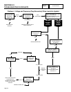
MATCH RESULTS WITH LETTER AND REFER TO FLOW CHART IN SECTION 2.3 “Problem 1”
è