


Page 14
Part 1
GENERAL INFORMATION
Section 1.3
non-PrePackaged interconnectionS
DISCUSSION:
On the current model air-cooled generators Wire 194
was changed to 15B. Wire 15B is still utilized for posi-
tive voltage for the transfer relay and Wire 23 is still the
control ground for transferring the generator. By follow-
ing the procedures below it is possible to connect new
product with Wire 15B to old or current product that
still utilize Wire 194, such as an RTS switch.
CONNECT A PRE-2008 LOAD CENTER SWITCH TO A
CURRENT OR FUTURE AIR-COOLED GENERATOR.
PROCEDURE:
1. Follow all instructions located in the Installation Manual
that was supplied with the unit regarding mounting of the
switch, junction box, and generator.
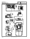
Note: When installing a standalone 5500 series
generator, the battery charger will be located in the
generator on the side of the control assembly.
2. Inside the Junction box between the generator and the
transfer switch there will be 5 wires coming from the
generator and 4 wires from the transfer switch.
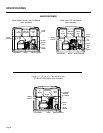
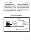
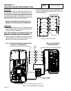
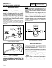
3. Using the following diagram and UL approved wire nuts
connect the following wires together. Wire 0 will not be
utilized for this setup.
WIRE NUTS
N1 (BLU)
N2 (YEL)
23 (BRN)
194 (ORG)
N1 (YEL)
N2 (YEL)
23 (WHT)
15B (RED)
0 (BLK)
CONTROL WIRES FROM
ENGINE GENERATOR
CONTROL WIRES FROM
TRANSFER SWITCH
Figure 1. Wire Connections
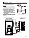
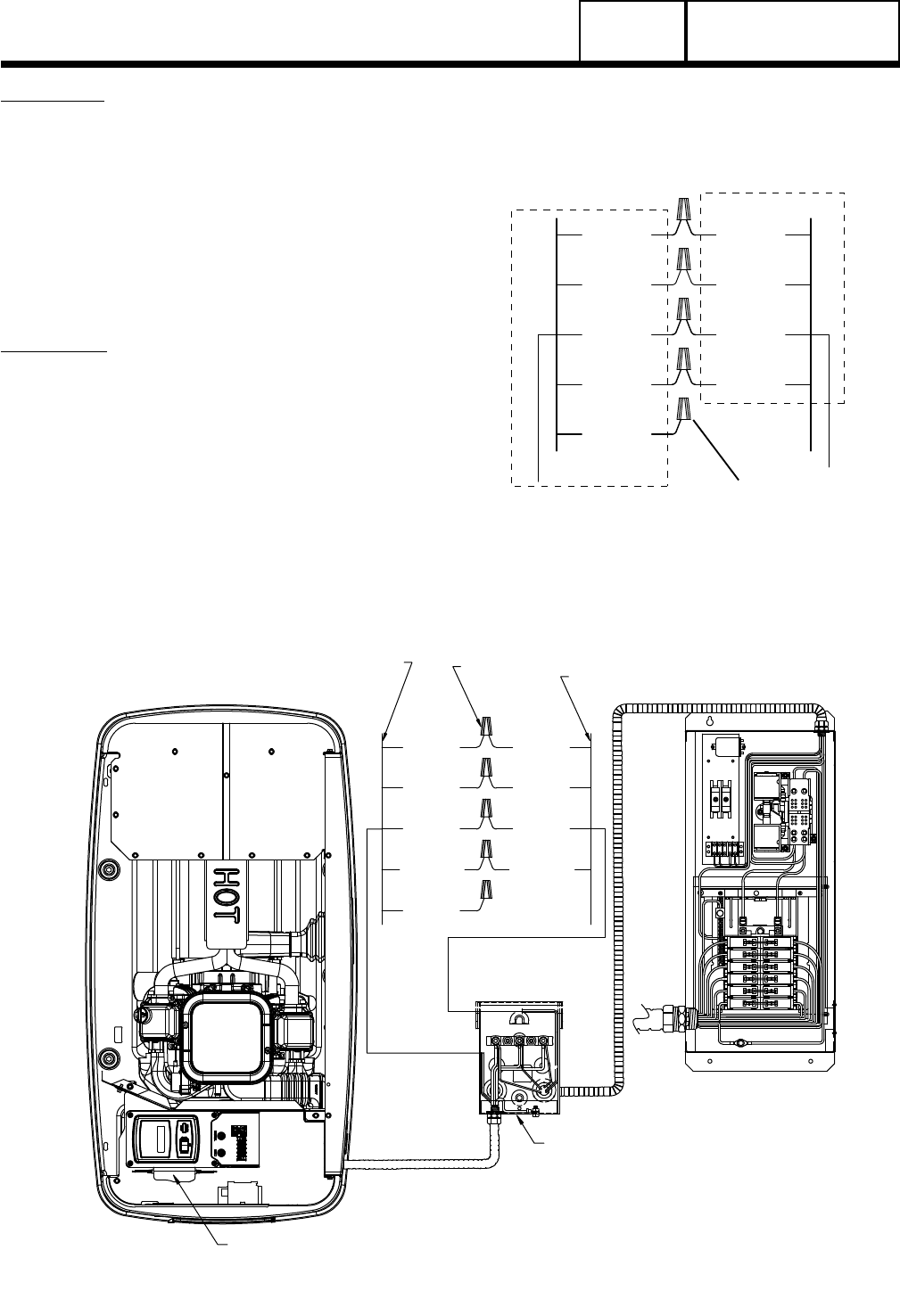
WIRE
NUTS
N1 (BLU)
N2 (YEL)
23 (BRN)
194 (ORG)
N1 (YEL)
N2 (YEL)
23 (WHT)
15B (RED)
0 (BLK)
CONTROL WIRES FROM ENGINE GENERATOR
“08” & LATER HSB AIR-COOLED GENERATORS
SINGLE & V-TWIN ENGINES
PRE “08” LOAD CENTER
TRANSFER SWITCH
EXTERNAL CUSTOMER
CONNECTION BOX
INSTALL BATTERY CHARGER GENERAC P/N 0G8023
CONTROL WIRES FROM TRANSFER SWITCH
Figure 2. Post 2008 HSB Interconnections