


Page 35
AC GENERATORS
SECTION 2.2
OPERATIONAL ANALYSIS
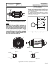
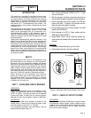
ROTOR RESIDUAL MAGNETISM
The generator revolving field (rotor) may be consid-
ered to be a permanent magnet. Some “residual”
magnetism is always present in the rotor. This residual
magnetism is sufficient to induce a voltage into the
stator AC power windings that is approximately 2-12
volts AC.
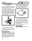
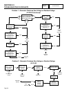
FIELD BOOST (12-20 KW)
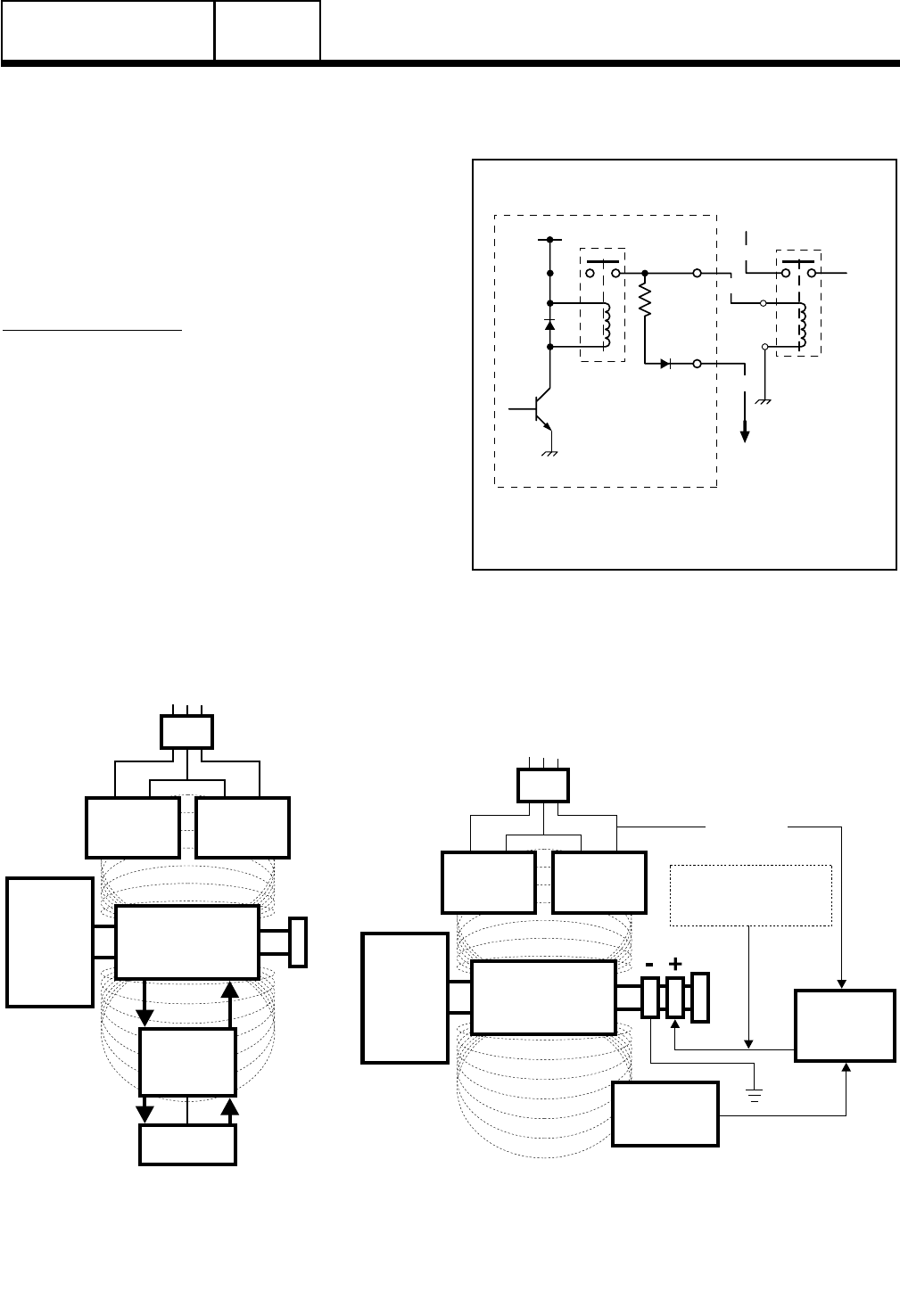
FIELD BOOST CIRCUIT:
When the engine is cranking, direct current flow is
delivered from a circuit board to the generator rotor
windings, via Wire 4.
The field boost system is shown schematically in
Figure 2. Manual and automatic engine cranking
is initiated by circuit board action, when that circuit
board energizes a crank relay. Battery voltage is then
delivered to field boost Wire 4 (and to the rotor), via
a field boost resistor and diode. The crank relay, field
boost resistor and diode are all located on the circuit
board.
Notice that field boost current is available only while
the crank relay is energized, i.e., while the engine is
cranking.
Field boost voltage is reduced from that of battery
voltage by the resistor action and, when read with a
DC voltmeter, will be approximately 9 or 10 volts DC.
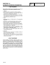
DIODE
PIN 5
PIN 1
BASE
TRANSISTOR
FIELD
BOOST
RESISTOR
FIELD
BOOST
DIODE
STARTER
CONTACTOR
TO
STARTER
+12 VDC
FIELD
BOOST
TO
ROTOR
CRANK
RELAY K1
CIRCUIT BOARD
56
4
13
Figure 2. Field Boost Circuit Schematic
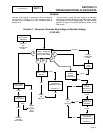
PART 2
STATOR
EXCITATION
WINDING
VOLTAGE
REGULATOR
FIELD BOOST FROM
CONTROL LOGIC
CIRCUIT BOARD
STATOR
POWER
WINDING
STATOR
POWER
WINDING
MAGNETIC
FIELD
MAGNETIC
FIELD
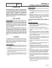
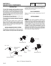
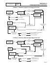
MLB = MAIN LINE CIRCUIT BREAKER
ROTOR
SENSING
TO LOAD
MLB
ENGINE -
DIRECT
DRIVE
12-20 kW Units
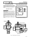
Figure 1. Operating Diagram of AC Generator
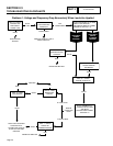
CAPACITOR
STATOR
EXCITATION
WINDING
STATOR
POWER
WINDING
STATOR
POWER
WINDING
MAGNETIC
FIELD
MAGNETIC
FIELD
MLB = MAIN LINE
CIRCUIT BREAKER
ROTOR
TO LOAD
MLB
ENGINE -
DIRECT
DRIVE
8/10 kW Units