


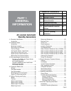

GENERAL INFORMATION
SECTION 1.3
NON-PREPACKAGED INTERCONNECTIONS
PART 1
CONNECT A 2008 AND LATER LOAD CENTER SWITCH
TO A PRE-2008 AIR-COOLED GENERATOR.
PROCEDURE:
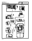
1. Follow all instructions located in the Installation Manual
that was supplied with the unit regarding mounting of the
switch, junction box, and generator.
Note: When installing a standalone pre-2008 gen-
erator, the battery charger will be located in the
generator utilizing the 12 VDC trickle charger.
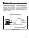
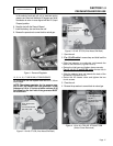
2. Inside the Junction box between the generator and the
transfer switch there will be 4 wires coming from the
generator and 5 wires from the transfer switch.
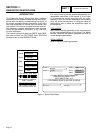
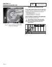
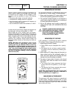
3. Using the following diagram and UL approved wire nuts
connect the following wires together. Wire 0 will not be
utilized for this setup.
Note: Remove the battery charger from the trans-
fer switch; it will not be utilized in the operation of
the generator.
WIRE NUTS
N1 (BLU)
N2 (YEL)
23 (BRN)
194 (ORG)
N1 (YEL)
N2 (YEL)
23 (WHT)
15B (RED)
0 (BLK)
CONTROL WIRES FROM
ENGINE GENERATOR
CONTROL WIRES FROM
TRANSFER SWITCH
Figure 3. Wire Connections
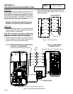
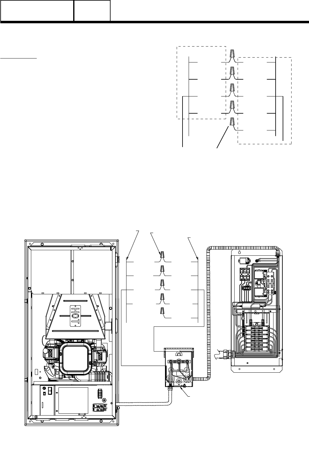
WIRE
NUTS
N1 (BLU)
N2 (YEL)
23 (BRN)
194 (ORG)
N1 (YEL)
N2 (YEL)
23 (WHT)
15B (RED)
0 (BLK)
CONTROL WIRES FROM ENGINE GENERATOR
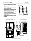
PRE “08” HSB AIR-COOLED GENERATORS
SINGLE & V-TWIN ENGINES
“08” & LATER LOAD CENTER
TRANSFER SWITCH
EXTERNAL CUSTOMER
CONNECTION BOX
CONTROL WIRES FROM TRANSFER SWITCH
Figure 4. Pre-2008 HSB Interconnections
Page 15