


SECTION 4.4
DIAGNOSTIC TESTS
Page 133
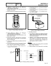
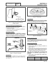
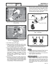
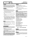
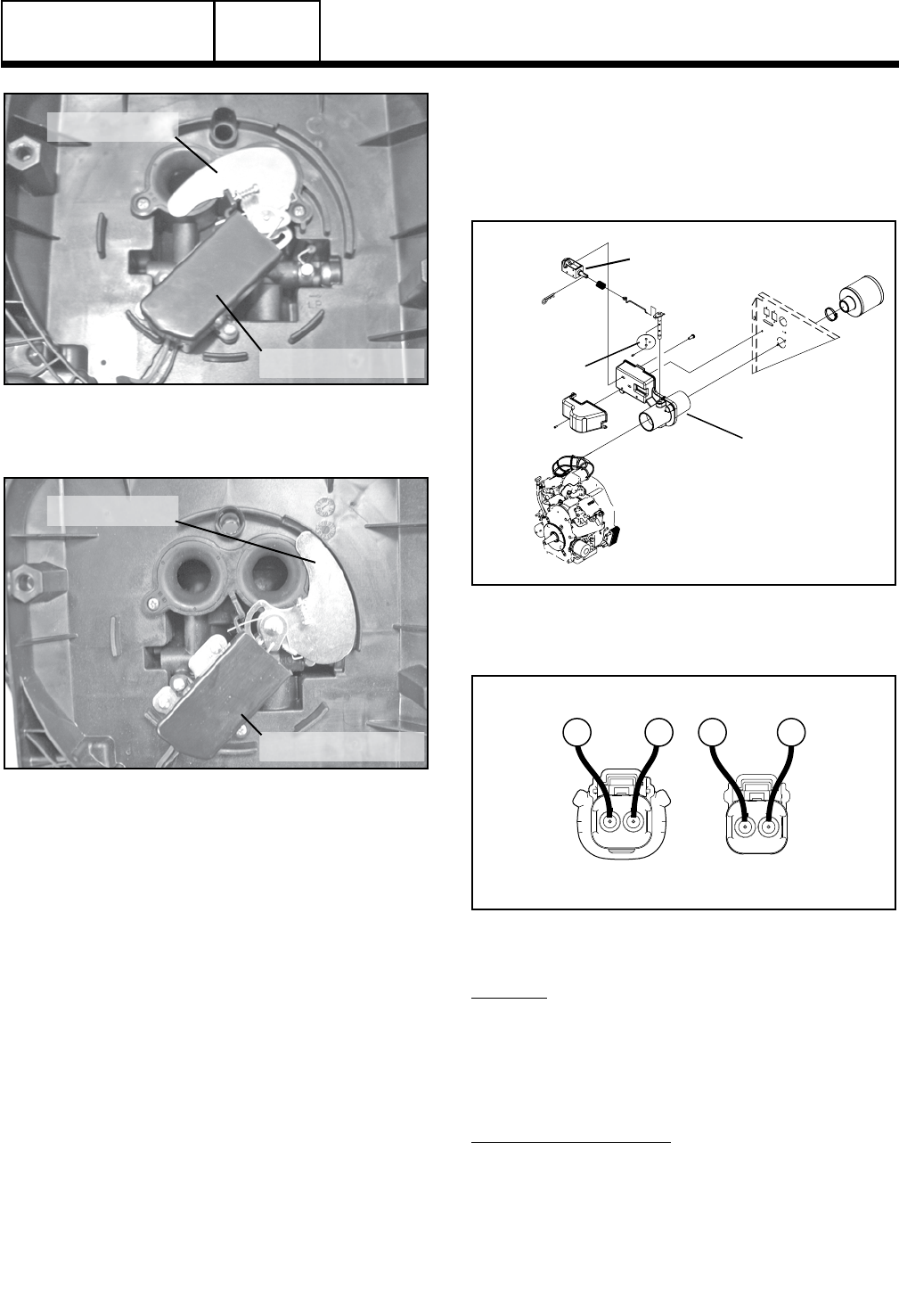
CHOKE SOLENOID
CHOKE PLATE
Figure 22. Solenoid De-Energized, Choke Closed
12-20 kW Units
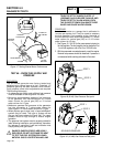
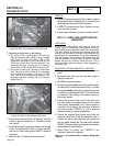
CHOKE SOLENOID
CHOKE PLATE
Figure 23. Solenoid Energized, Choke Open
12-20 kW Units
3. Set a VOM to measure DC voltage.
4. Connect the positive (+) test lead to Wire 14 (Pin 1) of the
C3 Connector going to the control panel (Female Side).
Connect the negative (-) test lead to Wire 90 (Pin 2).
5. Set the AUTO-OFF-MANUAL Switch to MANUAL. While
cranking, battery voltage should be measured cyclically.
If battery voltage was not measured, verify continuity
of Wire 90 between the C3 Connector and the printed
circuit board J1 Connector, Pin Location J1-23. Verify
continuity of Wire 14 between the C3 Connector and
J2 connector Pin Location J2-3. Repair or replace any
wiring as needed.
6. Disconnect C3 Connector. Set a VOM to measure resis-
tance. Connect the positive (+) test lead to Wire 14 (Pin
1) of C3 Connector going to the choke solenoid (Male
Side). Connect the negative (-) test lead to Wire 90 (Pin
2). Approximately 3.7 ohms should be measured.
7. With the generator running at a speed of approximately
60 Hertz, verify that the choke is energized and hold-
ing the choke plate open. Repeat Step 2 procedure,
however, once the unit starts, manually hold the choke
open while taking the voltage measurement.
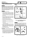
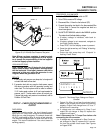
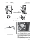
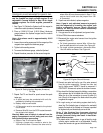
CHOKE PLATE
CHOKE SOLENOID
CHOKE HOUSING
Figure 24. Exploded View Showing Location of Choke
Plate - 10 kW Units
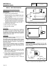
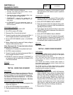
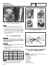
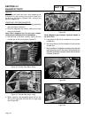
FEMALE SIDE
MALE SIDE
2 1
12
90
9014
14
Figure 25. C3 Choke Solenoid Connector
RESULTS:
1. If Battery voltage was not measured in Step 5 and wire
continuity is good, replace the printed circuit board.
2. If Choke Solenoid coil resistance is not measured in
Step 6, replace the Choke Solenoid.
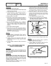
PROCEDURE: 8 kW UNITS
1. Operational Check: Set the AUTO-OFF-MANUAL
Switch to MANUAL. While cranking the choke solenoid
should energize and pull the choke plate closed. If the
choke solenoid does not pull in, verify that the choke
can be manually closed. There should be no binding or
interference.
DC CONTROL
PART 4