


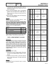
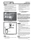
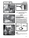
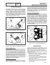
STEPPER MOTOR
PULL ARM THIS
DIRECTION TO
CLOSE THROTTLE
Figure 11. Throttle Positions 9/10 kW Units
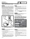
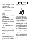
STEPPER MOTOR
STEPPER MOTOR ARM
PULL ARM THIS
DIRECTION TO
CLOSE THROTTLE
Figure 12. Throttle Positions 9/10 kW Units
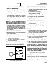
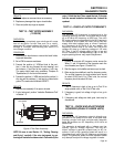
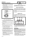
STEPPER MOTOR
STEPPER MOTOR ARM
PULL ARM THIS
DIRECTION TO
CLOSE THROTTLE
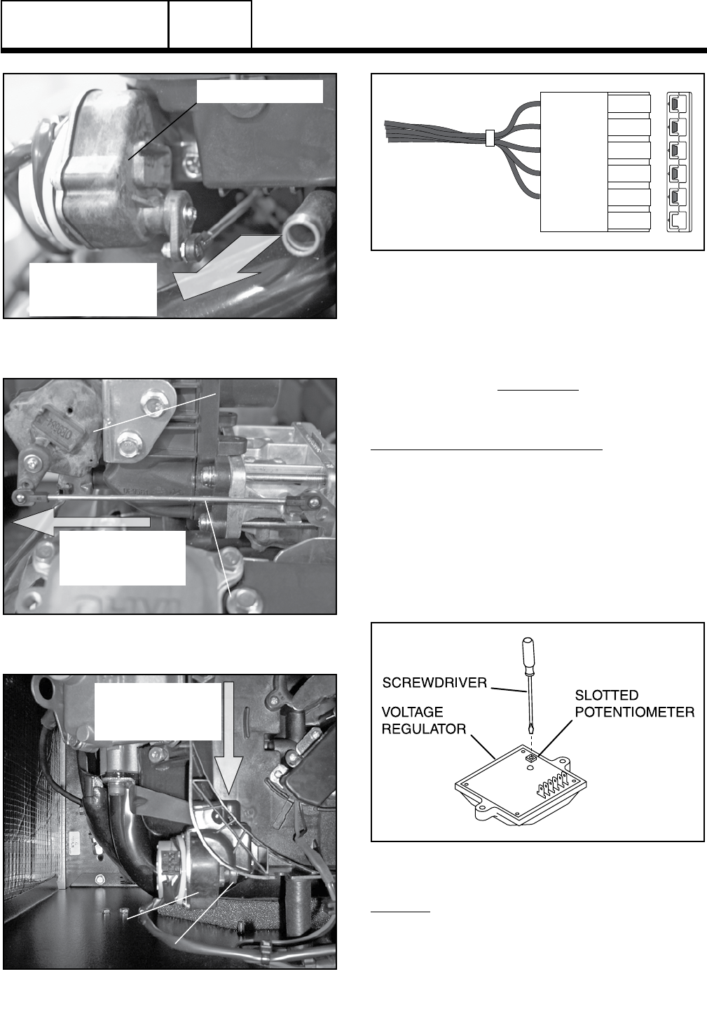
Figure 13. Throttle Positions 12-20 kW Units
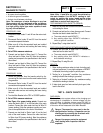
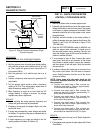
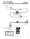
RED
EMPTY
YELLOW
BROWN
ORANGE
BLACK
Figure 14. Six Pin Connector Wire Colors
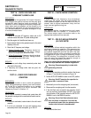
TEST 17 – CHECK AND ADJUST VOLTAGE
REGULATOR (12-20 KW)
DISCUSSION:
For additional information, refer to description and
components Section 2.1.
PROCEDURE (V-TWIN ENGINE UNITS):
With the frequency at 60 Hertz, slowly turn the
slotted potentiometer (Figure 15) until line voltage
reads 247-249 volts.
NOTE: The access panel on top of the control panel
must be removed to adjust the voltage regulator.
NOTE: The voltage regulator is housed in the
back of the generator control panel. The regula-
tor maintains a voltage in direct proportion to
frequency at a 2-to-1 ratio. For example, at 60
Hertz, line-to-neutral voltage will be 120 volts.
Figure 15. Voltage Adjustment Potentiometer
RESULTS:
1. If the frequency and voltage are now good, discontinue tests.
2. If frequency is now good but voltage is high or low, refer
back to flow chart.
Page 51
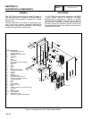
AC GENERATORS
SECTION 2.4
DIAGNOSTIC TESTS
PART 2