


AC GENERATORS
SECTION 2.3
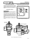
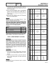
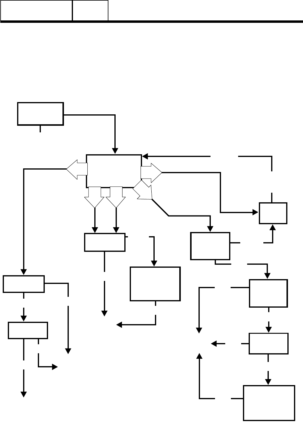
TROUBLESHOOTING FLOWCHARTS
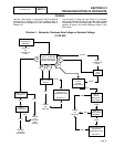
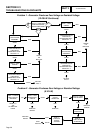
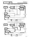
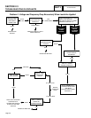
Use the “Flow Charts” in conjunction with the detailed
instructions in Section 2.4. Test numbers used in
the flow charts correspond to the numbered tests in
Section 2.4.
The first step in using the flow charts is to correctly
identify the problem. Once that has been done, locate
the problem on the following pages. For best results,
perform all tests in the exact sequence shown in the
flow charts.
PART 2
Page 37
GENERAL
REPAIR
OR
REPLACE
REPAIR
OR
REPLACE
REPAIR
OR
REPLACE
THEN
RETEST
REPLACE
VOLTAGE
REGULATOR
TEST 1 - CHECK
MAIN CIRCUIT
BREAKER
TEST 4 - PERFORM
FIXED EXCITATION /
ROTOR AMP DRAW
PERFORM STATOR
INSULATION
RESISTANCE TEST
-
SECTION 1.4
PERFORM ROTOR
INSULATION
RESISTANCE TEST
-
SECTION 1.4
TEST 7 - TEST
STATOR
TEST 5 - WIRE
CONTINUITY
TEST 6 -
FIELD BOOST
TEST 11 -
CHECK
ROTOR
RESISTANCE
CHECK
VOM
FUSES
TEST 12 -
CHECK
BRUSHES &
SLIP RINGS
TEST 13 -
TEST ROTOR
ASSEMBLY
REPAIR
OR REPLACE
FUSES
RE-TEST
BAD
BAD
BAD
BAD
BAD
BAD
BAD
BAD
GOOD
GOOD
GOOD
GOOD
Problem 1 - Generator Produces Zero Voltage or Residual Voltage
(12-20 kW)
D
G
A
C
B
GOOD
GOOD
RESET TO
“ON”
OR REPLACE
IF BAD