


SECTION 4.4
DIAGNOSTIC TESTS
Page 127
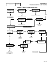
PROCEDURE:
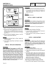
1. Set a VOM to measure DC voltage.
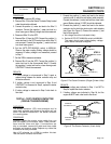
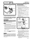
2. Remove Wire 13 from the Starter Contactor Relay located
under the printed circuit board.
3. Connect the positive (+) meter test lead to the Wire 13
connector. Connect the negative (-) meter test lead to a
clean frame ground. Battery voltage should be measured.
4. Reconnect Wire 13 to the SCR.
5. Remove Wire 16 from the SCR. Connect the positive (+)
meter test lead to the SCR terminal from which Wire 16
was removed. Connect the negative (-) meter test lead
to a clean frame ground.
6. Set the AUTO-OFF-MANUAL switch to MANUAL.
Observe the meter reading. Battery voltage should be
measured. If battery voltage is not measured, proceed
to Step 7.
7. Set the VOM to measure resistance.
8. Remove Wire 0 from the SCR. Connect the positive (+)
meter test lead to the disconnected Wire 0. Connect
the negative (-) meter test lead to a clean frame ground.
CONTINUITY should be measured.
RESULTS:
1. If battery voltage is not measured in Step 3, repair or
replace wiring between the starter contactor relay and
the starter solenoid.
2. If battery voltage is not measured in Step 6 and
CONTINUITY is measured in Step 8, replace the starter
contactor relay.
3. If battery voltage is measured in Step 6 refer back to
flow chart.
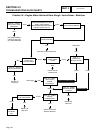
TEST 64 – TEST STARTER CONTACTOR
(SINGLE CYLINDER ENGINE)
DISCUSSION:
The starter contactor (SC) must energize and its
heavy duty contacts must close or the engine will not
crank. This test will determine if the starter contactor
is in working order.
PROCEDURE:
Carefully inspect the starter motor cable that runs
from the battery to the starter motor. Cable connec-
tions must be clean and tight. If connections are
dirty or corroded, remove the cable and clean cable
terminals and terminal studs. Replace any cable that
is defective or badly corroded.
Use a DC voltmeter (or a VOM) to perform this test.
Test the starter contactor as follows:
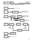
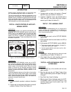
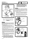
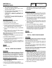
1. Connect the positive (+) meter test lead to the starter
contactor stud (to which the red battery cable connects).
Connect the common (-) meter test lead to a clean frame
ground. Battery voltage (12 VDC) should be indicated.
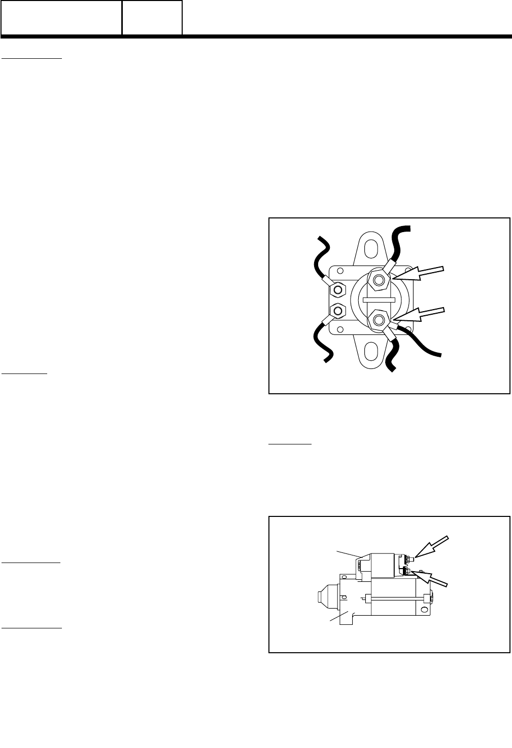
2. Connect the positive (+) meter test lead to the starter
contactor stud to which the starter motor cable attaches
(see Figure 8 or Figure 9). Connect the common (-) test
lead to frame ground.
a. No voltage should be indicated initially.
b. Set the AUTO-OFF-MANUAL switch to MANUAL.
The meter should now indicate battery voltage
as the starter contactor energizes.
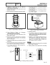
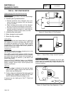
16
TO STARTER
STEP 2
TEST POINT
STEP 1
TEST POINT
13
TO BATTERY
13
TO FUSE (F1)
0
TO GROUND
56
TO ECB
Figure 8. The Starter Contactor (Single Cylinder Units)
RESULTS:
1. If battery voltage was indicated in Step 1, but NOT in
Step 2b, replace the starter contactor.
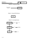
2. If battery voltage was indicated in Step 2b, but the
engine did NOT crank, refer back to flow chart.
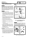
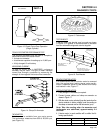
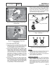
STARTER
CONTACTOR
STARTER
MOTOR
STEP 2
TEST POINT
STEP 1
TEST POINT
Figure 9. The Starter Contactor (V-twin Units)
DC CONTROL
PART 4