


TEST 18 – CHECK VOLTAGE AND
FREQUENCY UNDER LOAD
DISCUSSION:
It is possible for the generator AC output frequency
and voltage to be good at no-load, but they may drop
excessively when electrical loads are applied. This
condition, in which voltage and frequency drop exces-
sively when loads are applied, can be caused by (a)
overloading the generator, (b) loss of engine power, or
(c) a shorted condition in the stator windings or in one
or more connected loads.
PROCEDURE:
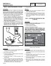
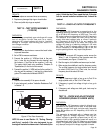
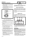
1. Connect an accurate AC frequency meter and an AC
voltmeter across the stator AC power winding leads.
2. Start the engine, let it stabilize and warm-up.
3. Apply electrical loads to the generator equal to the rated
capacity of the unit.
4. Check the AC frequency and voltage.
a. Single Cylinder Units: Frequency should not
drop below approximately 58 Hertz. Voltage
should not drop below about 230 volts.
b. V-Twin Engine Units: Frequency should not drop
below approximately 60 Hertz. Voltage should
not drop below about 240 volts.
RESULTS:
1. If frequency and voltage drop excessively under load,
refer back to flow chart.
2. If frequency and voltage under load are good, dis-
continue tests.
TEST 19 – CHECK FOR OVERLOAD
CONDITION
DISCUSSION:
An “overload” condition is one in which the generator
rated wattage/amperage capacity has been exceed-
ed. To test for an overload condition on an installed
unit, the best method is to use an ammeter. See
“Measuring Current” in Section 1.5.
PROCEDURE:
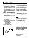
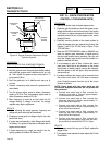
Use a clamp-on ammeter to measure load current draw, with
the generator running and all normal electrical loads turned on.
RESULTS:
1. If the unit is overloaded, reduce loads to the unit’s rated
capacity.
2. If unit is not overloaded, but rpm and frequency drop
excessively when loads are applied, go to Test 16.
TEST 20 – CHECK ENGINE CONDITION
DISCUSSION:
If engine speed and frequency drop excessively
under load, the engine may be under-powered. An
under-powered engine can be the result of a dirty air
cleaner, loss of engine compression, faulty fuel set-
tings, incorrect ignition timing, etc.
PROCEDURE:
For engine testing, troubleshooting and repair
procedures refer to Problem 11 in Section 4.3.
For further engine repair information refer to the
appropriate engine service manuals
.
TEST 21 – FIELD FLASH ALTERNATOR
(8-10 KW UNITS)
DISCUSSION:
The alternator utilizes residual magnetism within the
windings to charge the capacitor. If the generator has
been sitting for a long period of time with no activity
the residual magnetism could be lost within the rotor.
Field flashing the rotor while connected in parallel with
the capacitor will force a charge of electricity through
the DPE winding. The voltage that is induced into the
rotor will return and charge the capacitor enough to
take over voltage regulation of the unit.
Note: It is crucial that the generator exercise once
a week to help maintain this residual magnetism.
*
Warning:
Please keep safety in mind while
performing this test.
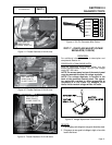
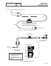
PROCEDURE:
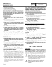
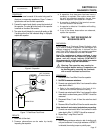
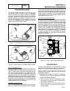
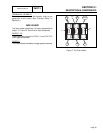
1. Construct an energizing cord that is similar to that shown
in Figure 17 and connect it as shown in Figure 18.
2. Set the AUTO-OFF-MANUAL switch to the OFF position.
*
Warning:
Do NOT energize the capacitor for
more than 1 second at a time.
3. Momentarily turn on the energizing cord (one second).
4. Disconnect the energizing cord from the capacitor.
5. If the field flash was successful, the generator should
now be producing approximately 240 VAC at the main
circuit breaker of the generator when the AUTO-OFF-
MANUAL is set to the MANUAL position.
*
Warning:
Do not field flash alternator more
than two times in sequence. If the unit has
not produced power after two attempts, other
issues exist and need to be addressed.
RESULTS:
1. Refer back to flow chart.
Page 52
PART 2
AC GENERATORS
SECTION 2.4
DIAGNOSTIC TESTS