


GENERAL INFORMATION
SECTION 1.4
PREPARATION BEFORE USE
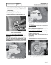
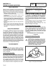
in the selector knob and pull out to overcome spring
pressure and then twist clockwise 90 degrees and allow
the selector to return in once aligned with the LP (Liquid
Propane) position.
6. Save this tool with the Owner's Manual.
7. Install the battery, door and close the roof.
8. Reverse the procedure to convert back to natural gas.
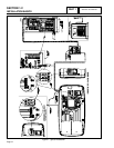
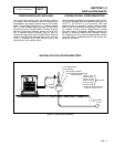
Figure 1. Demand Regulator
10, 12, 14, 16, 17 AND 20 KW, V-TWIN ENGINES:
To reconfigure the fuel system from NG to LP, follow
these steps:
NOTE: The primary regulator for the propane sup-
ply is NOT INCLUDED with the generator. A fuel
pressure of 10 to 12 inches of water column (0.36
to 0.43 psi) to the fuel inlet of the generator MUST
BE SUPPLIED.
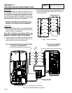
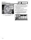
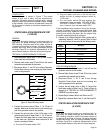
FUEL SELECTION
LEVER -
“IN” POSITION FOR
NATURAL GAS
Figure 2. 10 kW, GT-530 (Inlet Hose Slid Back)
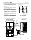
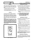
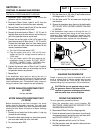
FUEL SELECTION
LEVER -
“OUT” POSITION FOR
LIQUID PROPANE
(VAPOR) FUEL
Figure 3. 10 kW, GT-530 (Inlet Hose Slid Back)
1. Open the roof.
2. For 10 kW units: Loosen clamp and slide back the
air inlet hose.
• Slide fuel selector on carburetor out towards the
back of the enclosure (Figures 2 and 3).
• Returntheinlethoseandtightenclampsecurely.
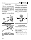
For 12, 14, 16, 17 and 20 kW units: remove the air
cleaner cover.
• Slidetheselectorleverouttowardsthebackofthe
enclosure (Figures 4 and 5).
• Return the air cleaner cover and tighten the two
thumb screws.
3. Close the roof.
4. Reverse the procedure to convert back to natural gas.
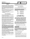
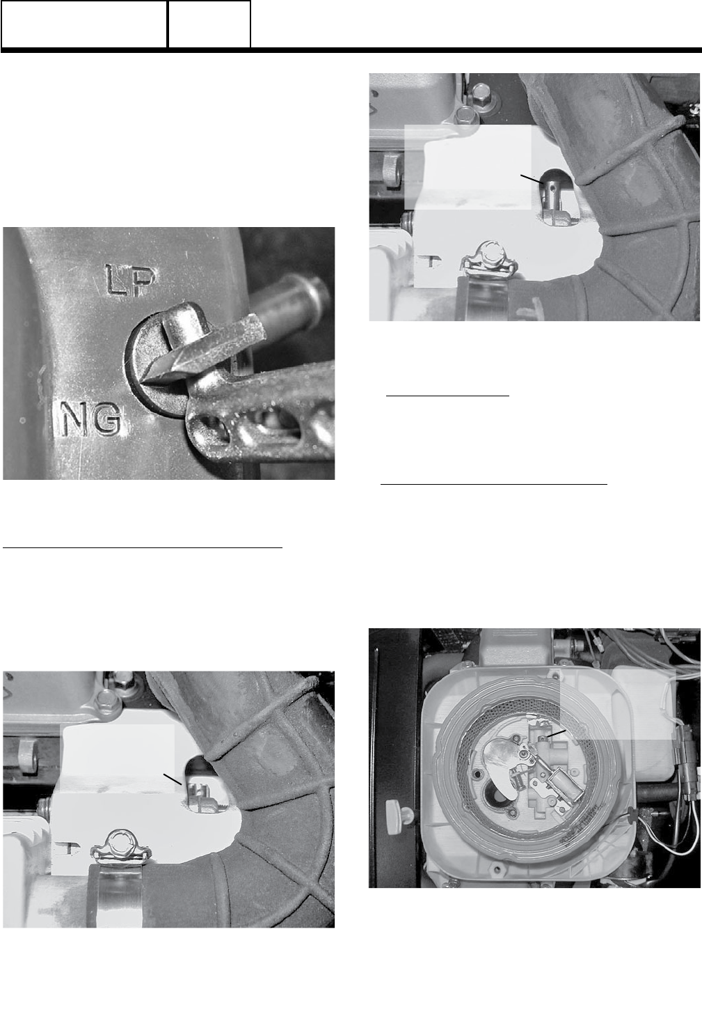
FUEL SELECTION
LEVER -
“IN” POSITION FOR
NATURAL GAS
Figure 4. 12/14/16/17/20 kW, GT-990/GT-999
(Airbox Cover Removed)
PART 1
Page 17