


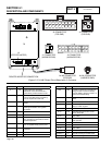
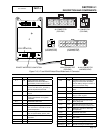
CONTROLLER DISPLAY
Ready to Run
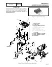
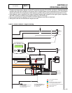
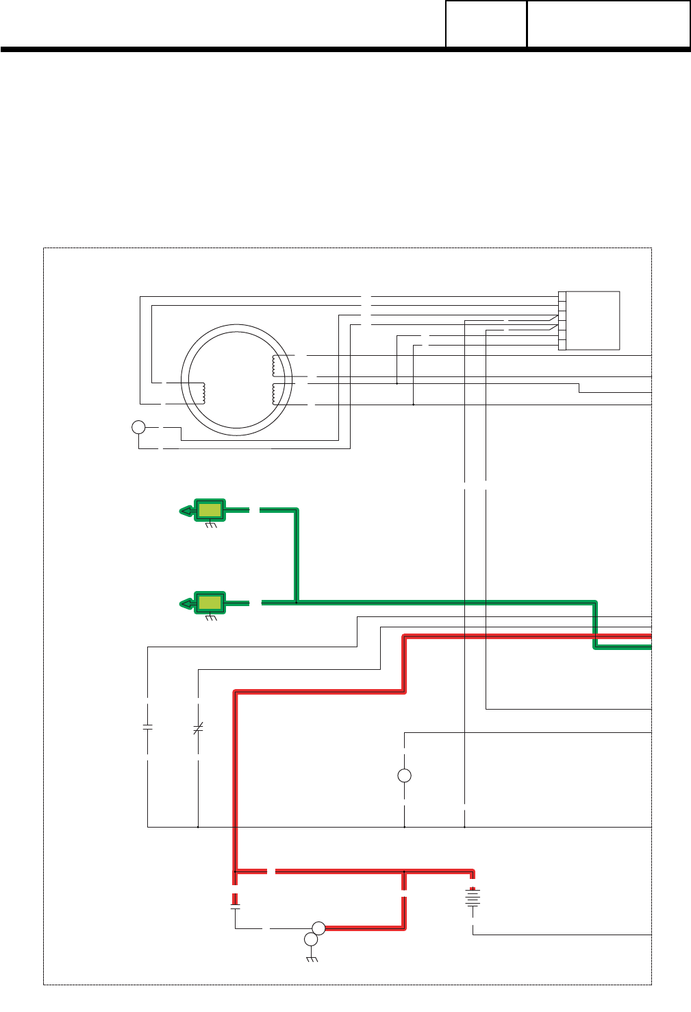
= 12 VDC ALWAYS PRESENT
= AC VOLTAGE
= GROUND FOR CONTROL PURPOSES
= 12 VDC DURING CRANKING ONLY
= 12 VDC DURING ENGINE RUN CONDITION
= DC FIELD EXCITATION
= 5 VDC TO LED
0
4
4
0
BA
6
11
22
6
2
2
REGULATOR
11
2
6
0
4
22
VOLTAGE
4
0
0
13
13
18
SP2
IM2
16
13
SCR
0
0
86
85
HTO
LOP
18
0
13
12V
BATTERY
SCR
SM
IM1
SP1
44
11
POWER
WINDING
33
22
WINDING
POWER
STATOR
4
0
56
0
SC
820
817
818
819
819
818
817
820
L2
L1
LED BOARD
4
3
2
1
4
ACTUATOR
GOVERNOR
14
14
90
OUTPUT
GENERATOR
240 VAC
NEUTRAL
INPUT
UTILITY
240 VAC
TRANSFER
+ BATTERY
GROUND
56015B23
23
0
0
FS
BATTERY WARMER
OPTIONAL
N1
00
22
33
11
44
CB
15B
14
0
0
CS
N2
N1
21
N2
N1
18
13
86
85
4
3
2
1
18171615141312109 1186 743 5
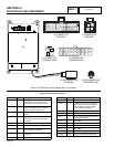
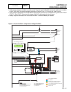
CB - CIRCUIT BREAKER, MAIN OUTPUT
HTO - HIGH TEMPERATURE SWITCH
FS - FUEL SOLENOID
LEGEND
SCR - STARTER CONTROL RELAY
SC - STARTER CONTACTOR
CS - CHOKE SOLENOID
LOP - LOW OIL PRESSURE SWITCH
SM - STARTER MOTOR
BA - BRUSH ASSEMBLY
IM_ - IGNITION MODULE
SP_ - SPARK PLUG
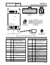
0
J3
J1
PRINTED CIRCUIT BOARD
TO
PCB
7.5 AMP FUSE
SELF RESETTING FUSE
CONTROLLER
J2
Page 104
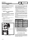
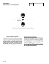
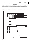
INTRODUCTION
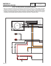
This “Operational Analysis” is intended to familiarize the service technician with the operation of the DC control
system on units with air-cooled engine. A thorough understanding of how the system works is essential to sound
and logical troubleshooting. The DC control system illustrations on the following pages represent a 14 kW unit.
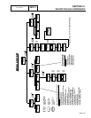
UTILITY SOURCE VOLTAGE AVAILABLE
See Figure 1, below. The circuit condition with the AUTO-OFF-MANUAL switch set to AUTO and with “Utility”
source power available can be briefly described as follows:
PART 4
DC CONTROL
SECTION 4.2
OPERATIONAL ANALYSIS