AC GENERATORS
SECTION 2.4
DIAGNOSTIC TESTS
PROCEDURE:
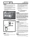
1. Consult the owner’s manual of the meter being used for
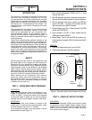
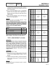
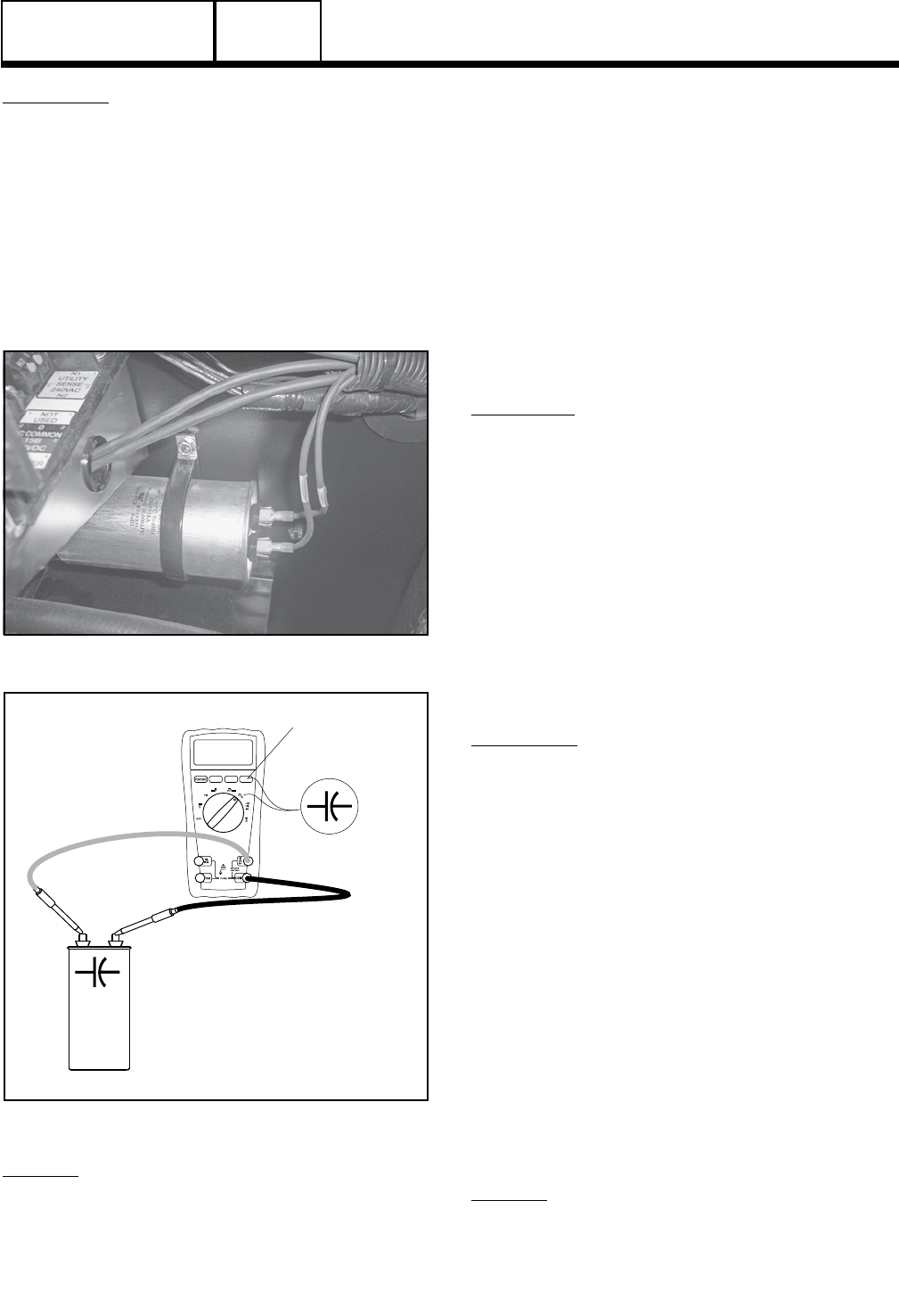
directions on measuring capacitance. Figure 7 shows a
typical meter and how to check capacitance.
2. Connect the meter leads directly across the terminals of
the capacitor. The rated µf (micro farad) of the capacitor
is marked on the side of the canister.
3. The meter should display the correct µf reading ± 5µf.
If anything other than the indicated rating is displayed,
replace the capacitor.
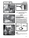
Figure 6. Capacitor
SET TO READ
CAPACITANCE
CAPACITOR
+
+
-
-
59.0
µf
Figure 7. Field Boost Test Points
RESULTS:
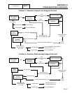
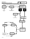
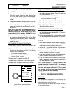
1. Refer back to flow chart
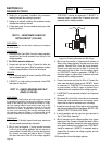
2. Common observations can be made by visually
inspecting the capacitor.
a. A capacitor that has gone bad can have a
tendency to explode. Use caution when deal-
ing with an exploded capacitor, the gel from
inside a capacitor can cause skin irritation.
b. A capacitor is defective if the terminal connec-
tions are loose on the canister.
c. A capacitor is defective if it wobbles while sitting
on a flat surface.
d. If any of the above observations are observed,
replace the capacitor.
TEST 10 – TEST DPE WINDING ON
BRUSHLESS UNITS
DISCUSSION:
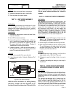
A DPE winding or Displaced Phase Excitation wind-
ing is used to charge a capacitor that discharges and
charges releasing a voltage that is induced into the
rotor. If the DPE winding fails, only residual magnetism
of the rotor will be measured at the Main Breaker.
Note: The resistance of stator windings is very
low. Some meters will not read such a low resis-
tance, and will simply indicate CONTINUITY.
Recommended is a high quality, digital type meter
capable of reading very low resistances.
*
Warning: The capacitor may need to be
discharged before testing. A capacitor can
be discharged by crossing the terminals
with a metal insulated screw driver.
PROCEDURE:
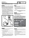
1. Disconnect Wire 2 and Wire 6 from the capacitor.
2. Set VOM to measure resistance.
3. Connect one meter lead to Wire 2 and connect the other
meter lead to Wire 6.
a. Refer to the specifications in the front of this
manual for the correct resistance reading.
4. Connect one meter lead to Wire 2 and connect the other
meter lead to a clean frame ground, INFINITY should be
measured.
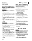
5. Disconnect Wires 11 and 44 from the main line circuit
breaker.
6. Disconnect Wire 22 and Wire 33 from the neutral connection
Note: Isolate all main stator leads before proceeding.
7. Connect one meter lead to Wire 2 and connect the other
meter lead to Wire 11. INFINITY should be measured.
8. Repeat Step 7 using Wires 2 and 44.
RESULTS:
1. Stator winding resistance values is a test of winding conti-
nuity and resistance. If a very high resistance or INFINITY
is indicated, the winding is open or partially open.
PART 2
Page 47


