


GENERAL INFORMATION
SECTION 1.2
INSTALLATION BASICS
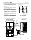
POWER SOURCE AND LOAD LINES
The utility power supply lines, the standby (genera-
tor) supply lines, and electrical load lines must all be
connected to the proper terminal lugs in the transfer
switch. The following rules apply: In 1-phase systems
with a 2-pole transfer switch, connect the two utility
source hot lines to Transfer Switch Terminal Lugs N1
and N2. Connect the standby source hot lines (E1,
E2) to Transfer Switch Terminal Lugs E1 and E2.
Connect the load lines from Transfer Switch Terminal
Lugs T1 and T2 to the electrical load circuit. Connect
UTILITY, STANDBY and LOAD neutral lines to the
neutral block in the transfer switch.
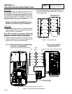
SYSTEM CONTROL INTERCONNECTIONS
Home standby generators are equipped with a termi-
nal board identified with the following terminals: (a)
UTILITY 1, (b) UTILITY 2, (c) 23, and (d) 15B. Load
centers house an identically marked terminal board.
When these four terminals are properly interconnect-
ed, dropout of utility source voltage below a preset
value will result in automatic generator startup and
transfer of electrical loads to the “Standby” source.
On restoration of utility source voltage above a preset
value will result in retransfer back to that source and
generator shutdown.
PART 1
Page 13
0000001
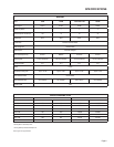
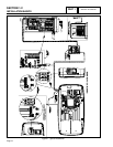
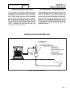
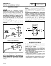
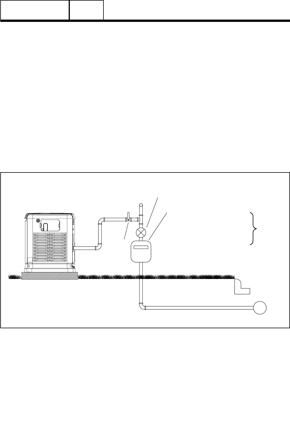
GAS MAIN
2-5 PSI
5-7” WC REGULATOR
TO HOUSEHOLD
GAS METER CAPABLE
+HOUSEHOLD APPLIANCES
FUEL FLOW OF:
OF PROVIDING NATURAL GAS
SAFETY
SHUT OFF
VALVE
(BASED ON 1000 BTU/CU FT)
BTU/HOUR
140,000 (7 kW)
156,000 (9 kW)
215,000 (12 kW)
220,000 (13 kW)
261,000 (16 kW)
294,000 (18 kW)
Figure 2. Proper Fuel Installation
NATURAL GAS FUEL INTERCONNECTIONS