


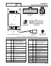
DC CONTROL
SECTION 4.1
DESCRIPTION AND COMPONENTS
PART 4
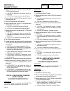
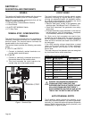
PIN WIRE CIRCUIT FUNCTION
J1-1 85 High temperature shutdown:
Shutdown occurs when Wire 85 is
grounded by contact closure in HTO
J1-2 86 Low oil pressure shutdown: Shutdown
occurs when Wire 86 is grounded by
loss of oil pressure to the LOP
J1-3 13 12 VDC source voltage for the circuit
board
J1-4 18 Ignition Shutdown: Circuit board
action grounds Wire 18 for ignition
shutdown.
J2-1 INTERNAL USE ONLY
J2-2 INTERNAL USE ONLY
J2-3 14 12 VDC output for engine run condi-
tion. Used for fuel solenoid and choke
solenoid operation.
J2-4 817 Grounded by printed circuit board to
turn on System Ready (Green) LED.
J2-5 23 Switched to ground for transfer relay
operation
J2-6 NOT USED
J2-7 NOT USED
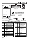
PIN WIRE CIRCUIT FUNCTION
J2-8 15B Provides an electrical connection for
charge current to reach the battery
from the battery charger. Provides 12
VDC to the Transfer Relay
J2-9 820 Positive voltage (+5 VDC) for status
LEDs.
J2-10 0 Common Ground
J2-11 56 12 VDC output to starter contactor
relay for V-Twin engines
J2-12 NOT USED
J2-13 818 Grounded by board to turn on the
Alarm (Red) LED.
J2-14 NOT USED
J2-15 90 Switched to ground for choke sole-
noid operation
J2-16 INTERNAL USE ONLY
J2-17 NOT USED
J2-18 NOT USED
J3 Control wires for Stepper Motor
Wired Plug-1 N1 240 VAC sensing for control board.
Wired Plug-2 N2 240 VAC sensing for control board.
Page 99
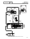
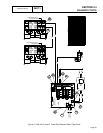
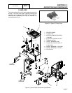
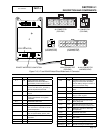
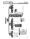
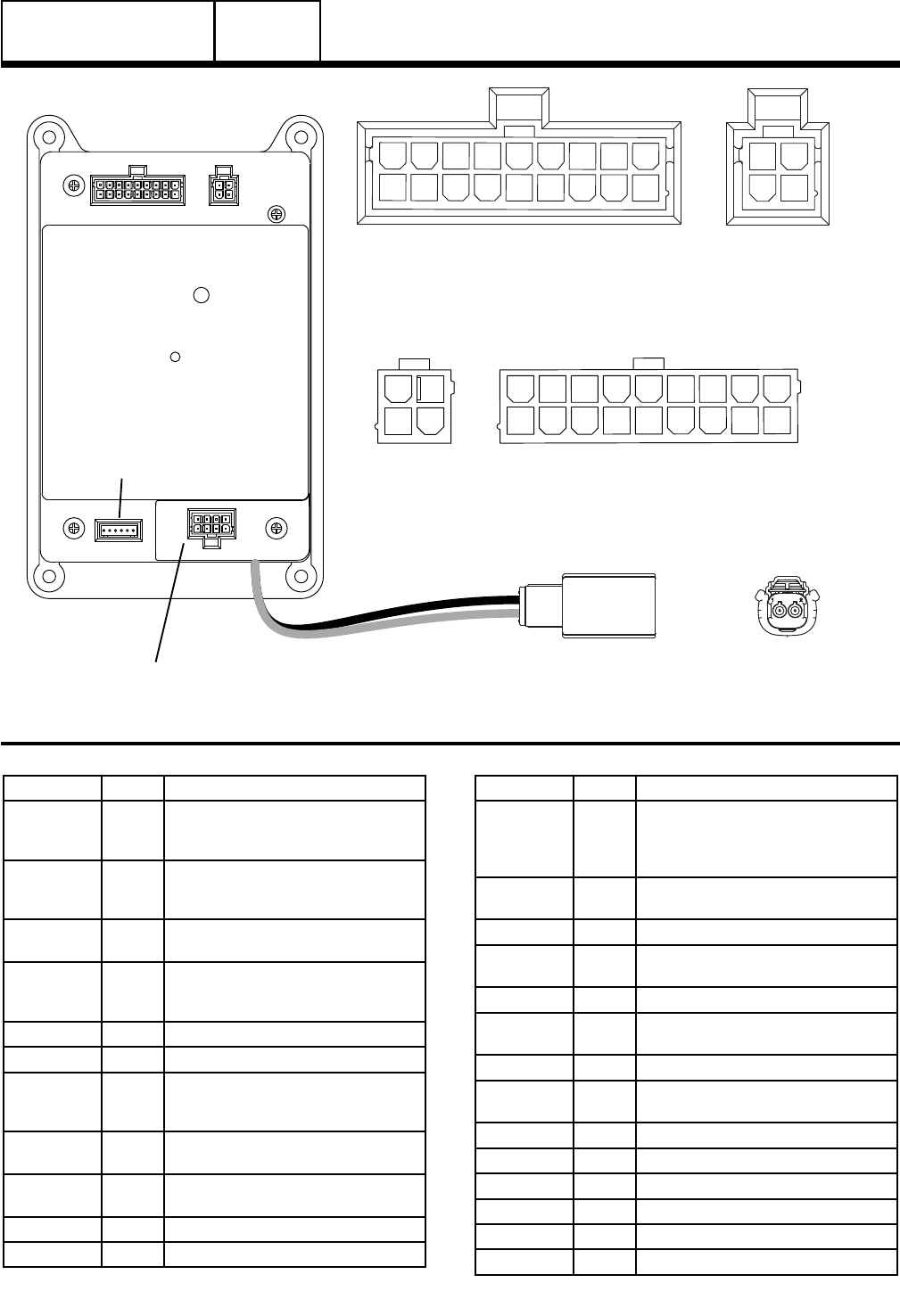
10 kW J1 Connector Pin Descriptions
J2
J3
(STEPPER MOTOR)
REMOTE WIRELESS CONNECTION
J1
J2 CONNECTOR
(HARNESS END)
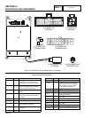
10 11 12 13 14 15 16 17 18
1 2
3 4
1 2
3 4 5 6 7 8 9
101112131415161718
12
34
123456789
101112131415161718
12
34
12
3456789
J1 CONNECTOR
(HARNESS END)
J2 CONNECTOR
(PCB END)
J1 CONNECTOR
(PCB END)
N1/N2 CONNECTOR
(HARNESS END)
N1/N2 CONNECTOR
(PCB END)
1 2
Figure 5. 10 kW Printed Circuit Board and J1 Connector