


SECTION 4.4
DIAGNOSTIC TESTS
Page 143
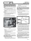
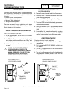
PROCEDURE: (INTAKE AND EXHAUST)
Make sure that the piston is at Top Dead Center
(TDC) of it’s compression stroke (both valves
closed). The valve clearance should be 0.05-0.1mm
(0.002-0.004 in.) cold.
Check and adjust the valve to rocker arm clearance
as follows:
1. Remove the four (4) screws from the rocker cover.
2. Remove the rocker cover and rocker cover gasket.
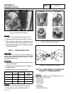
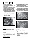
3. Loosen the rocker arm jam nut. Use a 10mm allen wrench
to turn the pivot ball stud and check the clearance
between the rocker arm and the valve stem with a flat
feeler gauge (see Figure 44).
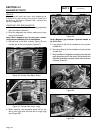
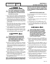
4. When the valve clearance is correct, hold the pivot ball
stud with the allen wrench and tighten the rocker arm
jam nut. Torque the jam nut to 174 inch pounds. After
tightening the jam nut, recheck the valve clearance to
make sure it did not change.
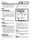
0.076 mm
(0.003") SHIM
JAM NUT
BALL STUD
Figure 44
5. Re-install the rocker cover gasket, rocker cover and
the four (4) screws.
RESULTS:
Adjust valve clearance as necessary, then retest.
TEST 78 – CHECK WIRE 18 CONTINUITY
DISCUSSION:
During cranking and running the printed circuit board
receives a pulse from the ignition magnetos via Wire
18. This signal has an AC voltage of 4-6 volts on
V-Twin engines only. If this signal is not received by
the printed circuit board the unit will shut down due to
no RPM sensing.
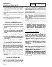
PROCEDURE: (V-TWIN ONLY)
1. Set a VOM to measure AC voltage.
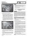
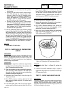
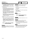
2. Connect one meter test lead to Wire 18 that is connected
to the bolt connector shown in Figure 46. Connect the
other meter test lead to a clean frame ground.
3. Set the AUTO-OFF-MANUAL switch to the MANUAL
position.
4. When the generator comes up to rated speed, measure and
record the voltage reading. 4-6 VAC should be measured.
5. If the correct voltage was not measured in Step 4, refer
back to flow chart. If the correct voltage was measured,
proceed to Step 6.
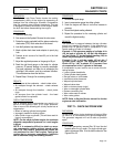
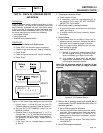
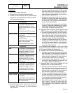
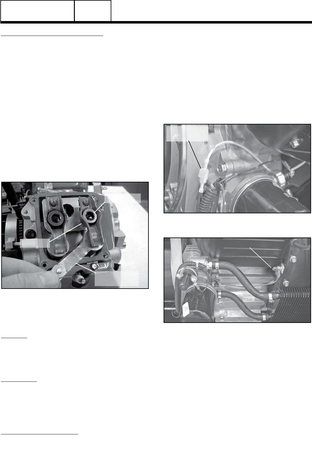
WIRE 18
CONNECTION
Figure 45. Wire 18 Connection 8 kW Units
WIRE 18 CONNECTION
Figure 46. Wire 18 Connection 10-20 kW Units
6. Set a VOM to measure resistance.
7. Disconnect the J1 Connector from the printed circuit
board.
8. Verify the continuity of Wire 18. Connect one meter
test lead to a clean frame ground. Connect the other
meter test lead to Pin Location J1-4 for all models. A
reading of 275K - 325K ohms should be measured. If
CONTINUITY is measured (0.1 ohms) a short to ground
could be present.
9. Disconnect Wire 18 from the stud connector. Continue to
leave J1 disconnected from Step 7.
DC CONTROL
PART 4