


Page 87
TRANSFER SWITCH
SECTION 3.4
DIAGNOSTIC TESTS
PART 3
a. If 115 Ohms is measured, proceed to Step 10.
b. If zero resistance or CONTINUITY is measured,
connect the meter test leads across Terminals
A and B on the transfer relay (TR1)
c. If zero resistance is measured, a short exists.
Replace TR1.
d. If 115 Ohms is measured, repair or replace
Wire 15B between the generator and the
transfer switch.
8. Set VOM to measure resistance.
9. Disconnect the J2 connector from the printed circuit board.
10. Measure across point M and pin location J2-8 of the con-
nector just removed. Continuity should be measured.
a. If continuity is not measured, repair or replace
Wire 15B between the J2 connector and the
terminal strip.
b. If continuity is measured and the pin connection
looks good, the internal fuse on the PCB has
failed. Replace printed circuit board.
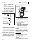
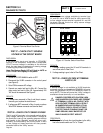
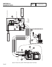
TEST 43 – CHECK BATTERY CHARGER
SUPPLY VOLTAGE
“RTSN & RTSE TRANSFER SWITCH”
DISCUSSION:
The battery charger is supplied with 120 VAC. The
output of the battery charger is 13.4 VDC/2.5A.
PROCEDURE:
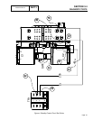
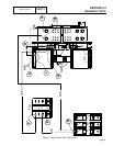
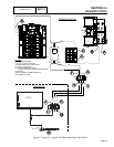
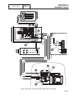
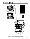
Refer to Figure 12 or Figure 12A.
1. Set VOM to measure AC voltage.
2. Measure across points A and B. 240 VAC should be
measured.
a. If 240 VAC is not measured, verify load source
voltage.
b. If 240 VAC is measured, proceed to Step 3.
3. Measure across points A and C. 240 VAC should be
measured.
a. If 240 VAC is not measured, repair or replace
wire between fuse block and T1 terminal.
b. If 240VAC is measured, proceed to Step 4.
4. Measure across points A and D. 240 VAC should be
measured.
a. If 240 VAC is not measured, replace 5A fuse.
b. If 240 VAC is measured, proceed to Step 5.
5. Measure across points E and F. 120 VAC should be
measured.
a. If 120 VAC is not measured, repair or replace
supply wires BC line and BC 00.
b. If 120 VAC is measured, refer to flow chart.
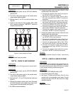
TEST 44 – CHECK BATTERY CHARGER
OUTPUT VOLTAGE
“RTSN & RTSE TRANSFER SWITCH”
DISCUSSION:
The battery charger is supplied with 120 VAC. The
output of the battery charger is 13.4 VDC/2.5A.
PROCEDURE:
Refer to Figure 12 or Figure 12A.
1. Set VOM to measure DC voltage.
2. Remove and isolate battery charger black and red leads
from generator terminal strip points G and H.
3. Measure across points G and H. Battery supply voltage
(12 VDC) should be measured.
a. If battery voltage is not measured, wait 5 minutes
and repeat Step 3. If battery supply voltage is still
not available, refer to Flow Chart.
b. If battery voltage is measured, proceed to Step 4.
4. Reconnect battery charger black and red lead wires
previously removed in Step 2.
5. Measure across points G and H. 13.4 VDC should be
measured.
a. If 13.4 VDC is not measured, replace the
battery charger
b. If 13.4 VDC is measured, the charger is working.
*NOTE : Battery charger voltage will be higher
than battery supply voltage.
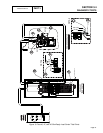
TEST 45 – CHECK WIRE 0/15B
“RTSN & RTSE TRANSFER SWITCH”
DISCUSSION:
In order for the battery charger to function, battery supply
voltage must be available to the battery charger.
PROCEDURE:
Refer to Figure 12 or Figure 12A.
1. Set VOM to measure DC voltage.
2. Remove and isolate battery charger black and red leads
from generator terminal strip points G and H.
3. Measure across points G and H on the terminal strip.
12VDC should be measured.
a. If 12 VDC is measured, the charger should be
functioning.
b. If 12 VDC is not measured, proceed to Step 4.
4. Remove Wire 0 and Wire 15B from generator terminal
strip locations G and H.
5. Wait five (5) minutes after removing wires.