


PROCEDURE:
1. On the generator panel, set the AUTO-OFF-MANUAL
switch to OFF.
2. Turn off the utility power supply to the transfer switch,
using whatever means provided.
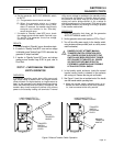
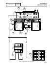
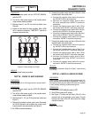
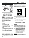
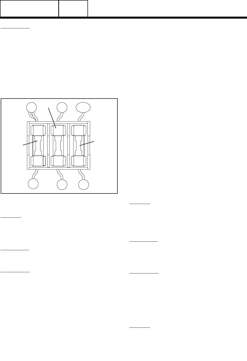
3. Remove fuses F1 and F2 from the fuse holder (see
Figure 8).
4. Inspect and test fuses for blown condition. With a VOM
set to measure resistance, CONTINUITY should be
measured across the fuse.
BLACK
T1
N1A N2A
N1
N2
F1
F3
F2
Figure 8. Fuse Holder and Fuses
RESULTS:
1. Replace blown fuse(s) as needed.
TEST 35 – CHECK N1 AND N2 WIRING
DISCUSSION:
A shorted Wire N1 or N2 to ground can cause fuse F1
or F2 to blow.
PROCEDURE:
1. On the generator panel, set the AUTO-OFF-MANUAL
switch to OFF.
2. Turn off the utility power supply to the transfer switch,
using whatever means provided.
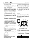
3. Remove fuses F1, F2, and F3 from the fuse holder (see
Figure 7).
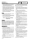
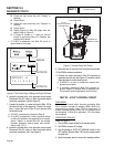
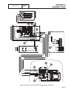
4. Remove the generator control panel cover. Disconnect
the N1/N2 connector that supplies the printed circuit
board located in the control panel (see Figure 6).
5. Set VOM to measure resistance.
6. Connect the positive meter test lead to Wire N1 at the
terminal block in the control panel.
a. Connect the negative meter lead to the ground
lug. INFINITY should be measured.
b. Connect the negative meter lead to Wire
23 at the terminal strip. INFINITY should be
measured.
c. Connect the negative meter lead to Wire 15B at
the terminal strip. INFINITY should be measured.
d. Connect the negative meter lead to Wire 0 at the
terminal strip. INFINITY should be measured.
e. Connect the negative meter lead to Wire N2 at the
terminal block. INFINITY should be measured.
f. Connect the negative meter lead to the neutral
connection. INFINITY should be measured.
7. Connect the positive meter test lead to Wire N2 at the
terminal block in the control panel.
a. Connect the negative meter lead to the ground
lug. INFINITY should be measured.
b. Connect the negative meter lead to Wire 23 at
the terminal strip. INFINITY should be measured.
c. Connect the negative meter lead to Wire 15B at
the terminal strip. INFINITY should be measured.
d. Connect the negative meter lead to Wire
0 at the terminal strip. INFINITY should be
measured.
e. Connect the negative meter lead to the neutral
connection. INFINITY should be measured.
RESULTS:
If a short is indicated in Step 6 or Step 7, repair wiring
and re-test.
TEST 36 – CHECK N1 AND N2 VOLTAGE
DISCUSSION:
Loss of utility source voltage to the generator will initi-
ate a startup and transfer by the generator. Testing at
the control panel terminal block will divide the system
in two, thereby reducing troubleshooting time.
PROCEDURE:
1. Set the AUTO-OFF-MANUAL switch to OFF.
2. Set a VOM to measure AC voltage.
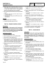
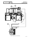
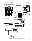
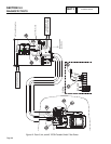
3. See Figure 9. Connect one test lead to Wire N1 at the
terminal block in the generator control panel. Connect
the other test lead to Wire N2. Utility line-to-line voltage
should be measured.
RESULTS:
Refer to Flow Chart
Page 83
TRANSFER SWITCH
SECTION 3.4
DIAGNOSTIC TESTS
PART 3