


Groundsmaster 3505--D Hydraulic SystemPage 4 -- 69
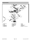
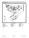
Removal (Fig. 43)
1. Park machine on a level surface, lower cutting units,
stop engine, engage parking brake and remove key
from the ignition switch.
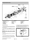
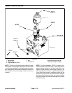
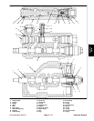
NOTE: The ports on the manifold are marked for easy
identification of components. Example: BV is the deck
circuit braking valveand P1is thegear pump connection
port (see Hydraulic Schematic to identify the function of
the hydraulic lines and cartridge valves at each port
location).
2. Thoroughly clean hydraulic manifold before doing
any disassembly.
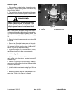
WARNING
Before disconnecting or performing any work
on the hydraulic system, all pressure in the
system must be relieved. See Relieving Hy-
draulic System Pressure in the General Infor -
mation section.
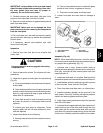
3. Label all hydraulic hoses and fittings for assembly
purposes. Also, mark fittings to allow correct assembly
orientation.
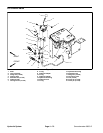
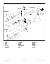
4. Remove hydraulic manifold from the machine using
Figure 43 as guide.
Installation (Fig. 43)
1. Install hydraulic manifold to the frame using Figure
43 as guide. Use labels and marks made during the re-
moval process to properly install hoses and fittings.
2. Make surehydraulic tank is full. Add correct oilif nec-
essary (see Traction Unit Operator’s Manual).
Hydraulic
System