


Rev. A
Groundsmaster 3505--D Page 6 -- 15 Chassis
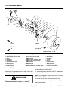
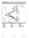
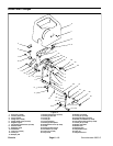
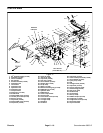
Disassembly (Fig. 9)
1. Park machine on a level surface, lower cutting units,
stop engine, engage parking brake and remove key
from the ignition switch.
2. Remove philips head screw and steering wheel cap
from the steering wheel.
3. Remove steering wheel nut from the steering control
valve. Pull steering wheel from the steering control
valve.
4. Remove steering cover (item 7) from the steering
control valve bracket.
5. Remove four (4) flange head screws securing the
steering control valve to the steering control valve
bracket.
6. Removeboth flange nuts,cap screws andpivot hubs
securing the steering control valve bracket to the steer-
ing arm. Slide bracket from the steering control valve
and steering arm.
7. Remove remaining parts as necessary to repair
steering column using Figure 9 as a guide. If steering
control valve requires service, see Steering Control
Valve in the Service and Repairs section of Chapter 4 --
Hydraulic System.
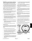
Assembly (Fig. 9)
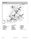
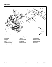
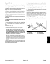
1. Make sure lever and friction discs are properly as-
sembled to the steering control valve bracket using Fig-
ures 9 and 10 as guides.
2. Position steering control bracket to the steering con-
trol valve and steering arm. Secure bracket to the steer-
ing arm with pivot hubs, cap screws and flange nuts.
3. Secure steering control valve bracket to the steering
control valve with four (4) flange head screws.
4. Secure steering cover to the steering control valve
bracket with washer head screws.
5. Install steering wheel to the steering control valve.
Torque steering wheel nut from 20 to 26 ft--lb (28 to 35
N--m).
6. Secure steering wheel cap to thesteering wheelwith
philips head screw.
1. Tilt bracket
2. Steering valve bracket
3. Jam nut
4. Flat washer
5. Friction disc
6. Steering tilt lever
7. Steering arm
Figure 10
1
3
4
5
7
6
2
Chassis