


Rev. A
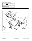
Groundsmaster 3505--DPage 7 -- 10Cutting Units
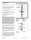
Rear Roller Service (Greasable Bearings with Bearing Nut)
Disassembly (Fig. 7)
1. Remove bearing lock nut from each end of roller
shaft.
2. Loosely secure roller assembly in bench vise and
lightly tap one end of roller shaft until outer seals and
bearing are removed from opposite end of roller tube.
Remove second set ofouter seals and bearing from roll-
er tube by tapping on opposite end of shaft. Remove
shaft from roller tube.
3. Carefully remove inner seal from both ends of roller
tube taking care to not damage tube surfaces.
4. Discard removed s eals and bearings.
5. Clean roller shaft and all surfaces on the inside of the
roller tube. Inspect components for wear or damage.
Also, carefully inspect seating surface and threads of
bearing lock nuts. Replace all damaged components.
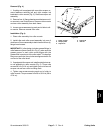
Assembly (Fig. 7)
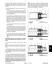
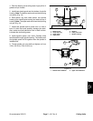
1. Install inner seals into roller tube making sure that
seal lip (and garter spring) faces end of tube. Use inner
seal tool(see Special Tools)and soft facehammer toful-
ly seat seals against roller shoulder (Fig. 8). Apply a
small amountof greasearound the lipof both inner seals
after installation.
IMPORTANT: During assembly process, frequently
check that bearings rotate freely and do not bind. If
any binding is detected, consider component re-
moval and reinstallation.
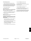
2. Install new bearing and outer seals into one end of
roller tube:
A. Position a new bearing into one end of roller tube.
Use bearing/outer seal tool (see Special Tools) with
a soft face hammer to fully seatbearing against roller
shoulder (Fig. 9). After bearing installation, make
sure that it rotates freely with no binding.
B. Apply a small amount of grease around the lip of
both outer seals.
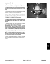
C. Install first outer seal into roller tube making sure
that seal lip (and garter spring) faces end of tube.
Use bearing/outer seal tool (see Special Tools) and
soft face hammer to lightly seat seal against roller
shoulder (Fig. 10). Make sure that bearing still freely
rotates after seal installation.
D. Using the same process, install second outer
seal makingsure tonot crush the installedouter seal.
Again, make sure that bearing still freely rotates.
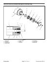
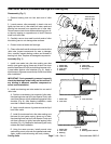
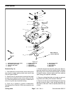
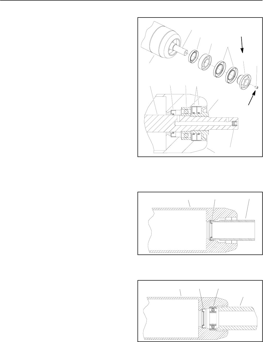
1. Roller tube
2. Roller shaft
3. Inner seal
4. Bearing
5. Outer seal
6. Bearing lock nut
7. Set screw
Figure 7
6
3
5
4
2
1
7
50 to 60 ft--lb
(68to81N--m)
6
3
5
4
2
1
7
Loctite #242
1. Roller tube
2. Inner seal
3. Inner seal tool
Figure 8
321
1. Roller tube
2. Inner seal
3. Bearing
4. Washer
5. Bearing/outer seal tool
Figure 9
321
4