


Rev. B
Groundsmaster 3505--D Hydraulic SystemPage 4 -- 89
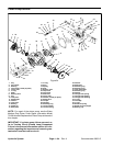
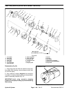
3. Clamp mounting flange of pump in a vise with the
shaft end down.
4. Loosen cap screws from the back plate.
5. Remove pump from the vise. Turn pump so that the
shaft end is facing down. Remove cap screws.
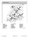
6. Remove back plate from the rear body.
7. Carefully remove rear body. Lift body straight up to
remove. Make sure the rear wear plate r emains on the
drive and idler gear shafts.R emove and discard o--rings
from the rear body.
IMPORTANT: Note position of the open and closed
side of the wear plates before removing from the
adapter plate. Also, identify wear plates (front and
rear) for proper reassembly. Do not scribe on wear
plates.
8. Carefully remove rear wear plate, idler gear, drive
gear and front wear plate from the adapter plate.
9. Remove coupler from the drive gear shaft.
10.Remove adapter plate.
11.Carefully remove front body. Lift body straight up to
remove. Make sure the rear wear plate r emains on the
drive and idler gear shafts.R emove and discard o--rings
from the front body.
IMPORTANT: Note position of the open and closed
side of the wear plates before removing from the
front plate.Also, identify wear plates(front and rear)
for properreassembly. Donot scribe on wearplates.
12.Carefully remove rear wear plate, idler gear, drive
gear and front wear plate from front plate.
13.Remove back--up gasket and pressure seal from all
wear plates.
NOTE: Gear pumpson early production machines may
have had ashaft seal and retainingring in the frontplate.
Pumps used on later production machines did not have
a seal or retaining ring. The seal and retaining ring are
not needed on any Groundsmaster 3505--D.
14.If retaining ring and seal exist in front plate, remove
them from the front plate. Make sure to not damage the
front plate counter bore when removing components.
15.Discard all removed seals and gaskets.
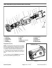
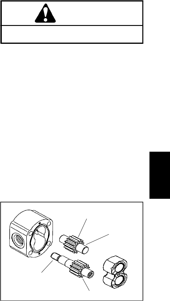
Inspection (Fig. 56)
1. Remove all nicks and burrs from all pump parts with
emery cloth.
CAUTION
Use eye protection such as goggles when using
compressed air.
2. Clean all parts with solvent. Dry all parts with com-
pressed air.
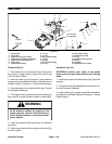
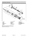
3. Inspect drive gears and idler gears for the following
(Fig. 58):
A. Drivegear shaftspline shouldbe freeof twistedor
broken teeth.
B. Gear shafts should be free of rough surfaces and
excessive wear at bushing points and sealing areas.
Scoring, rough surfaces or wear on gear shafts indi-
cates need for replacement.
C. Gear teeth should be free of excessive scoring
and wear. Any broken or nicked gear teeth must be
replaced.
D. Inspect gear face edge for sharpness. Sharp
edges of gears will mill into wear plates and, thus,
must be replaced.
1. Gear shaft spline
2. Gear shaft
3. Gear teeth
4. Gear face edge
Figure 58
3
4
1
2
4. Inspectgear bodies forexcessive scoring, gougesor
wear. Evidence of damage indicates need for compo-
nent replacement.
Hydraulic
System