Groundsmaster 3505--D Hydraulic SystemPage 4 -- 37
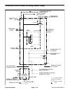
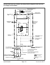
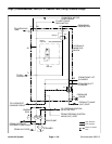
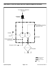
Procedure for Manifold Relief Valve (R1) Pressure
Test:
1. Make sure hydraulic oil is at normal operating tem-
perature.
2. Park machine on a levelsurface with the cuttingunits
lowered and off. Make sure engine is off and the parking
brake is engaged.
3. Read Precautions for Hydraulic Testing.
WARNING
Before disconnecting or performing any work
on the hydraulic system, all pressure in the
system must be relieved. See Relieving Hy-
draulic System Pressure in the General Infor -
mation section.
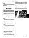
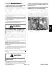
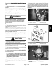
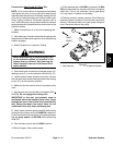
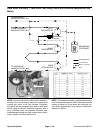
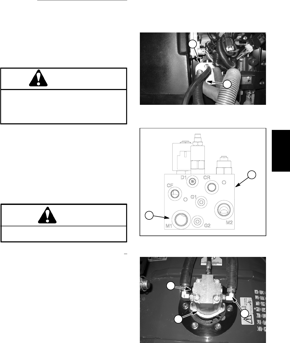
4. Disconnect hose connection from hydraulic fitting on
manifold port (M1) (Figure 22).
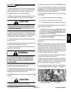
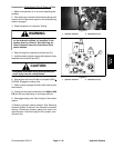
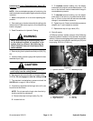
NOTE: Analternative to using manifoldport (M1) would
be to disconnect the inlet hydraulic hose to the front, left
deck motor. The motor inlet is opposite from the relief
valve on the motor (Figure 24).
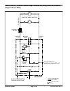
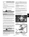
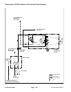
5. Install hydraulic tester (pressure and flow) in series
with the hose and hydraulic fitting. Make sure the flow
control valve on tester is fully open.
CAUTION
Keep awayfrom decks duringtest to prevent per-
sonal injury from the cutting blades.
6. Start engine and move throttle to full speed (3050 +
50 RPM). Engage the cutting units.
7. Watch pressure gauge carefully while slowly closing
the flow control valve to fully closed.
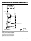
8. System pressure should be from 3350 to 3600 PSI
as the relief valve lifts.
A. If specification is not met, shut off engine and
clean or replace solenoid cartridge valve (R1) valve
(see Hydraulic Manifold Service in the Service and
Repairs section). Return to step 5.
B. If this specification is met, proceed to step 9.
9. Disengage cuttingunits. Shut off engine.Record test
results.
10.Relieve hydraulic system pressure (See Relieving
Hydraulic System Pressure in the General Information
section). Disconnect tester from manifold and hose.Re-
connect hydraulic hose that was disconnected for test
procedure.
1. Hydraulic manifold 2. Manifold port (M1)
Figure 22
2
1
1. Hydraulic manifold 2. Manifold port (M1)
Figure 23
1
2
1. Hydraulic deck motor
2. Inlet hose
3. Relief valve
Figure 24
2
1
3
Hydraulic
System


