


Groundsmaster 3505--D Hydraulic SystemPage 4 -- 79
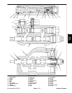
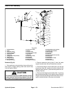
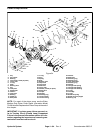
5. Remove cap screw (item 19) and flat washer (item
20) that secure the pump lever (item 29) and hub (item
21) assembly to the piston pump trunnion.
6. Separate pump lever (item 29) and hub (item 21) as-
sembly from pump trunnion and neutral bracket (item 5)
from mountplate. Locate andretrieve key from trunnion.
Installation (Fig. 50)
1. Install key into trunnion slot. Position neutral bracket
(item 5) to the mount plate and the pump lever (item 29)
and hub (item 21) assembly to the pump trunnion.
2. Secure pump lever (item 29) and hub (item 21) as-
sembly to the piston pump trunnion with flat washer
(item 20) and cap screw (item 19).
3. Secure neutral bracket (item 5) to the pump mount
plate with flange head screw (item 7) and flange nut
(item 6). Secure neutral bracket to the piston pump with
both flange head screws (item 7).
4. Position three (3) flat washers (items 16 and 17) to
traction control cable end. Secure traction control cable
to the pump lever with cap screw (item 32) and lock nut
(item 27).
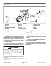
CAUTION
The extension spring is under tension and may
cause personal injury during installation. Use
caution when installing the spring to the pump
lever.
5. Install extension spring (item 3) to the cable support
bracket and neutral arm.
6. Adjust traction drive for neutral (see Traction Unit
Operator’s Manual).
Hydraulic
System