


Groundsmaster 3505--DPage 6 -- 8Chassis
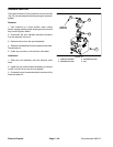
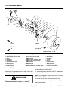
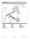
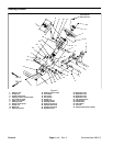
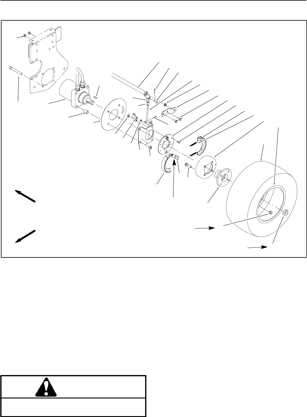
Front Wheels and Brakes
1. Lug nut (4 used per wheel)
2. Drive stud (4 used per wheel)
3. Wheel rim
4. Tire
5. Wheel hub
6. Lock nut
7. Hydraulic wheel motor
8. Brake drum
9. Woodruff key
10. Cotter pin
11. Adjustment rod
12. Brake lever
13. Lock nut (4 used per wheel)
14. Cap screw (4 used per wheel)
15. Brake bracket
16. Return spring (2 used per wheel)
17. Brake shoe (2 used per wheel)
18. Backing plate
19. Cam shaft
20. Retainer clip
21. Lock nut (4 used per wheel)
22. Socket head screw (4 used per wheel)
23. Spacer (4 used per wheel)
24. Wheel shield
25. Cotter pin
26. Clevis pin
27. Clevis
28. Jam nut
29. Flange bushing
30. Brake pivot bracket
31. Brake pivot shaft
32. Flange head screw (2 per wheel)
33. Flange nut (2 per wheel)
Figure 5
FRONT
RIGHT
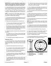
250 to 350 ft--lb
(339 to 474 N--m)
45 to 65 ft--lb
(61to88N--m)
10
28
31
30
32
29
3
8
2
6
4
1
14
13
24
12
27
26
25
11
15
21
5
18
19
20
16
17
17
7
23
22
33
9
Antiseize
Lubricant
Removal (Fig. 5)
1. Park machine on a level surface, lower cutting units,
stop engine, engage parking brake and remove key
from the ignition switch.
WARNING
Before jacking upthe machine, reviewand follow
Jacking Instructions in Chapter 1 -- Safety.
2. Jack up front wheel and use jack stands or blocking
to keep the front tire off the floor.
3. Remove lug nuts from drive studs. Pull wheel from
drive studs and wheel hub.
NOTE: The installation torque of the lock nut is from
250 to 350 ft--lb (339 to 474 N--m). Use impact wrench
to remove lock nut from the hydraulic motor shaft.
4. Remove lock nut from the hydraulic motor shaft. Re-
lease parking brake.